
User's Manual

Connector Locations
DRAFT
SC300 1X BTS Hardware Installation, ATP, and FRU Procedures
JAN 2002
6-2
Connector Locations for
MicroCell and Primary Surge
Suppressor
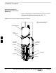
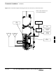
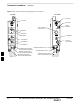
Figure 6-1 though Figure 6-3 show the location of the cable connectors
on the Microcell and Primary Surge Suppressor. The system
configuration determines which connectors are used.
Figure 6-1: General Block Diagram Showing the Port Names
SITE I/O
JUNCTION BOX
DC POWER
BREAKER
DC INPUT
MIB C
MIB B
MIB A
ANTENNA A
AC POWER
BREAKER
AC INPUT
SU RF
SU DIGITAL
ANTENNA B
SUBSCRIBER UNIT
NOTE: CABLES REMOVED FOR
ILLUSTRATION PURPOSES
6