
User's Manual

RGPS Cabling for Multiple BTS Sites Equipped with Optional Primary
Surge Suppressor
– continued
JAN 2002
5-27
SC300 1X BTS Hardware Installation, ATP, and FRU Procedures
DRAFT
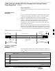
Table 5-21: Procedure to Install RGPS Cabling for an Outdoor Installation
Step Action
5 When you cut the cable in step 2, the jacketing for the portion of cable X on the unprotected side
of the surge suppressor is not grounded. To ground this portion of cable X, connect the drain wire
to a lug terminal tied directly to the master ground of BTS N.
NOTE
Only ground the end of the cable jacket at BTS N. Do not ground the jacket at BTS N+1. Refer
to Figure 5-19.
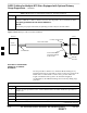
6 Cut cable X to a maximum distance of 5m from BTS N+1.
7 Ground the surge protection device to the master ground of BTS N+1.
8 When you cut cable X in step 6, the jacketing for the portion of cable X between BTS N+1 and
the newly–inserted surge protector is ungrounded. To ground this portion of cable X, connect the
drain wire from one end of the jacket of the cable to a lug terminal tied directly to the master
ground of BTS N+1. Refer to Figure 5-19.
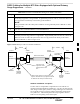
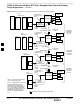
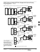
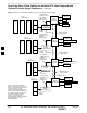
Figure 5-19: RGPS Sync Cable for Outdoor Installations
SITE I/O
INTERFACE
BTS N
BTS N+1
7.5 K OHM, 1W
RESISTOR
Attach the drain wires to the earth grounds. The
length of cable between surge suppressors should
be attached to the earth ground at BTS N only.
RGPS SYNC CABLE
SITE I/O
INTERFACE
SURGE
SUPPRESSOR
SURGE
SUPPRESSOR
Ground the surge
suppressors to the
master grounds at each
BTS
5M MAX
MASTER
GROUND
BTS N+1
MASTER
GROUND
BTS N
5M MAX
LUG
TERMINAL
LUG
TERMINAL
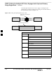
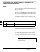
Outdoor installation exceptions
In cases where it is impossible or impractical to route cable X in a
continuous stretch from BTS N to BTS N+1, you may cut and rejoin the
cable using an inline splice (solder or crimp). Both types of connections
are acceptable as long as each wire remains electrically isolated from
every other wire. The twisted pairs must be kept together. Refer to
Table 5-22 for the pairing of the twisted pairs.
5