
User's Manual

RGPS Cabling for Multiple BTS Sites Equipped with Optional Primary
Surge Suppressor
– continued
DRAFT
SC300 1X BTS Hardware Installation, ATP, and FRU Procedures
JAN 2002
5-26
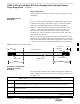
Table 5-20: Procedure to Install RGPS Cabling for an Indoor Installation
Step Action
4 Remove excess cable length from cable X and terminate to the sync forward lines on the Site I/O
interface of BTS N+1. Refer to Table 5-23 for the cable X pinouts. Do not terminate the drain
wire to the ground at the Site I/O interface at BTS N+1.
wire to the ground at the Site I/O interface at BTS N+1.
NOTE
If necessary for proper strain relief, the jacketing of cable X may be cut back further.
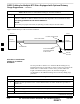
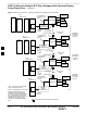
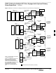
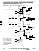
Figure 5-18: RGPS Sync Cable for Indoor Installation
SITE I/O
INTERFACE
SITE I/O
INTERFACE
BTS N
BTS N+1
7.5 K OHM, 1W RESISTOR
ATTACH DRAIN WIRE
TO MASTER GROUND
OF BTS N ONLY
RGPS SYNC CABLE
LOOSE WIRES
LUG TERMINAL
MASTER
GROUND
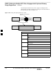
Procedure to Install RGPS
Cabling for an Outdoor
Installation
Use the procedure in Table 5-21 to install the RGPS cabling for any
installation that may be susceptible to surges or where any portion of the
RGPS cable is routed outside. In these cases, you must reduce the
length of the RGPS cable by (still to be determined length) to
accommodate for the additional timing error incurred by adding surge
protection.
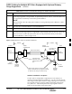
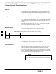
Table 5-21: Procedure to Install RGPS Cabling for an Outdoor Installation
Step Action
1 Follow all of the procedures in the “Connect RGPS Cables for Indoor Installation” procedure in
Table 5-20.
2 Cut cable X to a maximum distance of 5m from BTS N.
3 Install the surge protection device at this point, with the protected side towards BTS N.
4 Ground the surge protection device to the master ground of BTS N.
. . . continued on next page
5