
User's Manual
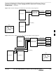
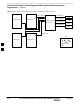

Site I/O, Span Line, RGPS, and Modem Cabling for Sites Equipped With
Primary Surge Suppressor
– continued
DRAFT
SC300 1X BTS Hardware Installation, ATP, and FRU Procedures
JAN 2002
5-22
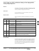
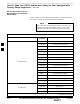
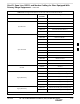
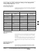
Table 5-14: Pin/Signal Information for Site I/O Cable and Punchdown Block
BTS Interface DescriptionPunchblock
Location
OSP 25T MODEM TIP
Phone (Modem)
OSP 25R MODEM RING
*Motorola recommends that you use the Customer Input 8 Signal and Ground for load center alarms.
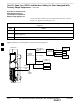
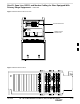
Connecting Customer–Defined
Inputs to the Primary Surge
Suppressor
The unit provides eight customer–defined inputs for connection to
external contacts. Each input (a signal/ground pair) is monitored for an
“OPEN” (>50 k Ohms) or “CLOSED” (<3 Ohms) condition.
Motorola recommends using Customer Input 8 Signal and Ground for
AC load center alarms. The Primary Surge Suppressor is shipped with
the AC load center alarms already connected to positions 1 and 2
(OSP8T and OSP8R). Refer to Figure 5-8 and Table 5-15.
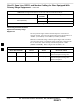
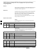
Table 5-15: Customer Alarm Wiring Positions in AC Load Center on MOVs
Alarm Wire Positions Circuit Alarm Reason for Alarm
1 2 Normally open Normally closed Damaged MOVs.
Power interruption to surge box
2 3 Normally closed Normally open Damaged MOVs.
Power interruption to surge box
Alarm interruption
5