
User's Manual

Antenna Cabling for Sites Equipped With Optional Primary Surge
Suppressor
JAN 2002
5-13
SC300 1X BTS Hardware Installation, ATP, and FRU Procedures
DRAFT
Objective
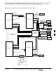
The objective of this procedure is to install the cabling for the
antenna(s).
The antenna cabling is installed between one or more units and the
Primary Surge Suppressor. No lightning arrestors are used.
Cable Labels
The cable designations are referenced to Table 4-1 in the “Cable
Description” area of this chapter.
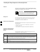
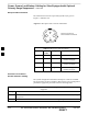
Required Cables
Table 5-9 provides the quantities and descriptions of the required cables.
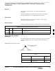
Table 5-9: Required Cables for Antenna Connections
Cable Qty. Part Number Description
C 1 to 8 Customer Supplied Antenna cable, 50–Ohm coaxial terminated with at least one male,
N–type connector.
D 2–6 Customer Supplied Antenna cable, terminated with 2 N–type connectors
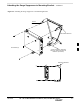
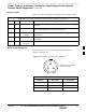
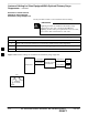
Antenna Cable Pin and Signal
Information
The antenna cabling uses a 50–Ohm coaxial cable. The inner conductor
provides signaling and the outer conductor provides shielding and
ground.
Figure 5-9: Antenna Cabling Details
OUTER
CONDUCTOR
INNER
CONDUCTOR
ANTENNA CABLE (COAXIAL)
CONNECTOR
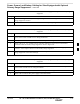
Table 5-10: Pin and Signal Information for Cables C and D (Antenna
Cable)
Antenna Inner Conductor Outer
Conductor
B (Microcell only) TX/RX Ground
A RX (Microcell) Ground
5