Cabling Overview Overview This chapter provides the procedures to prepare the BTS site cabling, but not attach it to the unit. Chapter 6 shows the scope of work for unit cabling. You will connect cables to the site and route them to the BTS location. You will attach the cables to the unit in Chapter 6. Repeat cabling installation as necessary for each unit at the BTS. NOTE Cabling is one of the most noticeable aspects of workmanship.
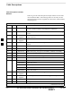
Cable Descriptions Cable Descriptions and Part Numbers Table 4-1 gives the cable descriptions and part numbers for the cables used to install the BTS. The following cables are necessary for sites equipped with the customer–supplied Site I/O Interface and the Primary Surge Suppressor. Table 4-1: Cable Descriptions and Part Numbers Cable Qty. Part Number A 1 3087701C02 Ground cable, 8 -AWG, insulated copper wire. Requires one ring lug connector. Used for Primary Surge Suppressor Installation.
Cable Descriptions – continued Table 4-1: Cable Descriptions and Part Numbers Cable Qty. Part Number S 1–4 3087854C02 T 1 Customer Supplied U 1 3087854C04 V 1 Customer Supplied Phone (Modem) cable. 22–24 AWG solid copper twisted pair. W 1–3 Customer Supplied Span Line Daisy Chain cable. X 1–11 3086039H18 RGPS Synchronization cable (part of kit SGKN4351A). 3086039H19 RGPS Synchronization cable (part of kit SGKN4352A).
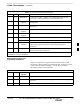
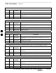
Cable Descriptions – continued Table 4-3: MicroCell Expansion Kit for Units 1 to 2 Long MIB A (Non–Cubicle) – T448A Cable Qty. Motorola Part Number Description n/a 2 5882106P01 50 Ohm Antenna Terminator A 1 3087701C02 Ground cable, 8 -AWG, insulated copper wire. Requires one ring lug connector. E 1 3087707C03 MIB A cable (current, 2m; micro) Table 4-4: MicroCell (800 MHz) Expansion Kit for Units 2 to 3 Current 2m MIB B – T448AR Cable Qty.
Cable Descriptions – continued Table 4-8: MicroCell Expansion Kit for Units 3 to 4 Current 2m MIBs A and C – T448H Cable Qty. Motorola Part Number Description A 1 3087701C02 Ground cable, 8 -AWG, insulated copper wire. Requires one ring lug connector. n/a 2 5882106P01 50 Ohm Antenna Terminator E 1 3087707C03 MIB A cable (current, 2m; micro) G 1 3087707C05 MIB C cable (current, 2m) Table 4-9: MicroCell Expansion Kit for Units 3 to 4 Longer 5M MIBs A and C – T448G Cable Qty.
Site Cabling for BTS With Customer–Supplied Site I/O Interface Preparing Site Cabling Scope of Work Figure 4-1 through Figure 4-4 shows the scope of work to be performed for preparing the site cabling with the customer–supplied Site I/O Interface. Chapter 6 shows the scope of work for unit cabling.
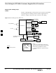
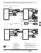
Site Cabling for BTS With Customer–Supplied Site I/O Interface – continued Figure 4-2: Site Cabling for Two MicroCells U/1(DC POWER) S/1(AC POWER) B/1 (GROUND) D/1(ANTENNA) MICROCELL 1 Y/1(GROUND) DC POWER AC INSTALL BOX (SEE NOTE 3) LA AC POWER ANT 1 TX/RX LA GROUND P/1 (SU) M/1 (RGPS) RGPS LA N/1 (SPAN) DSU LA SPAN O/1 (CUSTOMER INPUT) CUSTOMER INPUTS Z/1 (SITE I/O CABLE) SEE NOTES 1 AND 2 SITE I/O INTERFACE V/1 (PHONE) LA 4 PHONE (MODEM) E/1 (MIB) OR K/1 (MIB) U/1(DC POWER) S/1(AC
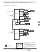
Site Cabling for BTS With Customer–Supplied Site I/O Interface – continued Figure 4-3: Site Cabling for Three MicroCells F/1 (MIB) OR I/1 (MIB) U/1(DC POWER) U/1(DC POWER) S/1 (AC POWER) DC POWER AC INSTALL BOX (SEE NOTE 3) D/1(ANTENNA) LA ANT 4 TX/RX LA ANT 3 RX MICROCELL 3 D/1(ANTENNA) LA S/1 (AC POWER) DC POWER AC INSTALL BOX (SEE NOTE 3) AC POWER LA AC POWER B/1 (GROUND) MICROCELL 1 D/1(ANTENNA) Y/1(GROUND) Y/1(GROUND) GROUND GROUND M/1 (RGPS) P/1 (SU) ANT 1 TX/RX LA RGPS LA P
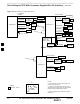
Site Cabling for BTS With Customer–Supplied Site I/O Interface – continued Figure 4-4: Site Cabling for Four MicroCells F/1 (MIB) OR I/1 (MIB) U/1(DC POWER) U/1(DC POWER) S/1 (AC POWER) MICROCELL 4 DC POWER AC INSTALL BOX (SEE NOTE 3) D/1(ANTENNA) LA AC INSTALL BOX (SEE NOTE 3) AC POWER B/1 (GROUND) D/1(ANTENNA) GROUND Y/1(GROUND) P/1 (SU) P/1 (SU) E/1 (MIB) OR K/1 (MIB) OR Z/1 (SITE I/O CABLE) SEE NOTE SITE I/O INTERFACE G/1 (MIB) OR J/1 (MIB) GROUND RGPS LA DSU O/1 (CUSTOMER INPUTS)
Power, Ground, and Battery Cabling for Sites Equipped with Customer–Supplied Site I/O Interface Objective The objective of this procedure is to install the power, earth ground, and battery cabling for one or more Microcell units at a site equipped with customer–supplied Site I/O Interface. WARNING Dangerous voltages, capable of causing death, are present in this equipment. Use extreme caution when handling and testing this equipment.
Power, Ground, and Battery Cabling for Sites Equipped with Customer–Supplied Site I/O Interface – continued The power and battery configurations for the MicroCell units are: AC power only (no battery) AC power with short duration battery DC power NOTE Neither the ”+” or ”–” terminal of the DC Input is connected to the BTS ground. If a negative supply input is provided, the ”+” terminal of the DC input must be connected to the Master Ground Plate (MGP).
Power, Ground, and Battery Cabling for Sites Equipped with Customer–Supplied Site I/O Interface – continued Table 4-13: AC Input Cable Information Connector Wire Color Description A Black Line B Green Ground C White Neutral DC Input Cable Information The information for the DC input cable(s) (Cable U) is given in Figure 4-6.
Power, Ground, and Battery Cabling for Sites Equipped with Customer–Supplied Site I/O Interface – continued Table 4-15: Procedure to Install Earth Ground Cable Step Action 1 Route cable Y (ground cable) from the ground on the mounting bracket to the customer defined grounding location. 2 Connect cable Y to the customer defined master ground plate.
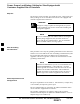
Power, Ground, and Battery Cabling for Sites Equipped with Customer–Supplied Site I/O Interface – continued Figure 4-7: AC Installation Box TERMINAL BLOCK 1–IN AC CONDUIT TO MICROCELL LOCATION LINE NEUTRAL GROUND CUSTOMER AC INPUT AC POWER CABLE CONNECTOR CUSTOMER POWER CONNECTIONS 4 NOTE: Shown with door removed for clarity Table 4-19: Procedure to Install DC Input Cable(s) Step 4-14 Action 1 Connect the loose wires of cable U (DC input cable) to the customer defined DC power source.
Antenna Cabling for Sites Equipped with Customer–Supplied Site I/O Interface Objective The objective of this procedure is to install the cabling for the antenna(s). This cabling is installed between one or more units and the customer–supplied lightning arrestor(s). Cable Labels The cable designations are referenced to Table 4-1 in the “Cable Description” area of this chapter. Required Cables Table 4-20 provides the quantities and descriptions of the required cables.
Antenna Cabling for Sites Equipped with Customer–Supplied Site I/O Interface – continued Route the antenna cable between the unit and the customer–supplied lightning arrestor. Refer to Figure 4-9 and Table 4-21. If a lighting arrestor is not required, route the cabling directly to the antenna.
Antenna Cabling for Sites Equipped with Customer–Supplied Site I/O Interface – continued Figure 4-11: Antenna Cabling for Three MicroCells C/1(ANTENNA) LA MICROCELL 3 ANT 4 TX/RX C/1(ANTENNA) LA LA ANT 1 TX/RX ANT 3 RX KEY LIGHTNING LA = ARRESTOR B/1(ANTENNA) C/1(ANTENNA) MICROCELL 1 MICROCELL 2 C/1(ANTENNA) LA ANT 2 TX/RX NAME NUMBER OF CABLES LABEL Figure 4-12: Antenna Cabling for Maximum of Four MicroCells MICROCELL 4 C/1(ANTENNA) MICROCELL 3 C/1(ANTENNA) LA LA ANT 4 TX/RX ANT 3 TX/
Site I/O , Span Line, RGPS and Modem Cabling for Sites Equipped with Customer–Supplied Site I/O Interface Objective The objective of this procedure is to install the Site I/O cable between the Site I/O junction box and the customer–supplied Site I/O interface. This procedure also covers the installation of the site cabling of the span line, RGPS and modem cabling to the site I/O interface.
Site I/O , Span Line, RGPS and Modem Cabling for Sites Equipped with Customer–Supplied Site I/O Interface – continued Procedure to Install Site I/O Cable Between Site I/O Junction Box and Site I/O Interface Route the Site I/O junction box cable from the unit location(s) to the Site I/O Extender Cable (cable Z). Route cable Z to the Site I/O interface. Connect the appropriate connectors within the Site I/O interface. Refer to Figure 4-13 and Table 4-23.
Site I/O , Span Line, RGPS and Modem Cabling for Sites Equipped with Customer–Supplied Site I/O Interface – continued Pin and Signal Information for Site I/O Cabling Table 4-23 gives the pin and signal information for the Site I/O cable.
Site I/O , Span Line, RGPS and Modem Cabling for Sites Equipped with Customer–Supplied Site I/O Interface – continued Table 4-23: Pin/Signal Information for Site I/O Cable BTS Interface Sync Forward Span (Network) Wire/Stripe Color Description Brown/Grey Data from Head – Brown/White Data from Head + Red/Black Data to Head – Red/Brown Data to Head + Red/Orange 1 PPS from Head – Red/Yellow 1 PPS from Head + Red/Green 1 PPS to Head – Red/Blue 1 PPS to Head + Red/Purple RGPS 28V Red/Grey
Site I/O , Span Line, RGPS and Modem Cabling for Sites Equipped with Customer–Supplied Site I/O Interface – continued Table 4-23: Pin/Signal Information for Site I/O Cable BTS Interface Span (Redundant) 4 Phone (Modem) Wire/Stripe Color Description Yellow/Green RX TIP Primary (Redundant) Yellow/Blue RX RING Primary (Redundant) Yellow/Purple TX TIP Primary (Redundant) Yellow/Grey TX RING Primary (Redundant) Yellow/White RX TIP Secondary (Redundant) Green/Black RX RING Secondary (Redundant)
Site I/O , Span Line, RGPS and Modem Cabling for Sites Equipped with Customer–Supplied Site I/O Interface – continued Connecting the RGPS Cable to the Site I/O Interface The RGPS (cable M) is connected to the Site I/O interface (Sync Forward) of the BTS. Table 4-24 provides the Sync Forward to RGPS connections.
RGPS Cabling for Multiple BTS Sites Objective This procedure gives information to connect multiple BTS sites for both RGPS (synchronous) and HSO (non–synchronous) configurations in both indoor and outdoor applications. Background The RGPS only connects to the first unit of a multi–unit logical BTS. This first unit sends timing signals to all other units. You only need to connect the site I/O interfaces of each multi–unit logical BTS to each other.
RGPS Cabling for Multiple BTS Sites – continued Surge suppressors Surge suppressors (Polyphaser 097–1017A–A.1) are required for certain installations. Cable Diagrams and Description Figure 4-18 shows the RGPS cabling for a multi–BTS configuration for an RGPS (synchronous) configuration. Figure 4-19 shows the RGPS cabling for a multi–BTS HSO (non–synchronous) configuration. Figure 4-14 shows the general construction of the RGPS Sync Cable (cable X). Cable X is supplied by Motorola with a 7.
RGPS Cabling for Multiple BTS Sites – continued Table 4-28: Procedure to Install RGPS Cabling for an Indoor Installation Step Action 4 Remove excess cable length from cable X and terminate to the sync forward lines on the Site I/O interface of BTS N+1. Refer to Table 4-31 for the cable X pinouts. Do not terminate the drain wire to the ground at the Site I/O interface at BTS N+1. NOTE If necessary for proper strain relief, the jacketing of cable X may be cut back further.
RGPS Cabling for Multiple BTS Sites – continued Table 4-29: Procedure to Install RGPS Cabling for an Outdoor Installation Step Action 5 When you cut the cable in step 2, the jacketing for the portion of cable X on the unprotected side of the surge suppressor is not grounded. To ground this portion of cable X, connect the drain wire to a lug terminal tied directly to the master ground of BTS N. NOTE Only ground the end of the cable jacket at BTS N. Do not ground the jacket at BTS N+1.
RGPS Cabling for Multiple BTS Sites – continued You must splice the drain wire as well. Apply a weatherproof heat shrink tubing or another weatherproof covering over the cable bundle in the spliced section. Refer to Figure 4-17. Figure 4-17: Cutting and Splicing RGPS Sync Cable Splice each wire including the drain wire.
RGPS Cabling for Multiple BTS Sites – continued Cable Connections For a full signal description of the Site I/O cable, refer to Table 4-23 in the “Site I/O, Span Line, RGPS and Modem Cabling” procedure. NOTE The wire colors are based on the Site I/O cable.
RGPS Cabling for Multiple BTS Sites – continued Figure 4-18: Site I/O Interface Cabling for RGPS (Synchronous) Configurations UNIT 301 UNIT 201 UNIT 101 UNIT 1 RGPS BTS 1 (SEE NOTE 1) SPAN SITE I/O CUSTOMER INPUTS SITE I/O INTERFACE ÇÇ ÇÇ PHONE (MODEM) SITE I/O CABLE UPSTREAM UNIT 201 UNIT 101 RGPS SYNC CABLE X UNIT 1 ÇÇ MAXIMUM DISTANCE IS 1 KM (SEE NOTE 2) DOWNSTREAM BTS 2 (SEE NOTE 1) SITE I/O SPAN SITE I/O INTERFACE CUSTOMER INPUTS ÇÇ ÇÇ 4 PHONE (MODEM) SITE I/O CABLE UPSTREA
RGPS Cabling for Multiple BTS Sites – continued Figure 4-19: Site I/O Interface Cabling for HSO (Non–Synchronous) Configurations UNIT 301 UNIT 201 UNIT 101 UNIT 1 BTS 1 (SEE NOTE 1) SPAN SITE I/O SITE I/O INTERFACE CUSTOMER INPUTS ÇÇ ÇÇ PHONE (MODEM) SITE I/O CABLE UPSTREAM X UNIT 201 UNIT 101 UNIT 1 RGPS SYNC CABLE ÇÇ ÇÇ MAXIMUM DISTANCE IS 600M (SEE NOTE 2 DOWNSTREAM BTS 2 (SEE NOTE 1) SITE I/O SPAN SITE I/O INTERFACE CUSTOMER INPUTS ÇÇ ÇÇ 4 PHONE (MODEM) SITE I/O CABLE UPSTR
Span Line Daisy Chain Cabling Objective The objective of this procedure is to install span line cabling between multiple BTS sites in an open daisy chain configuration. Background This feature allows up to 12 BTS sites to be linked together in an open daisy chain loop using a single T1/E1 span. This will reduce the number of spans necessary to support a CDMA system and minimize unused channels. Each multi–unit logical BTS may contain up to four units.
Span Line Daisy Chain Cabling – continued Figure 4-20: Site I/O Interface Cabling for Span Line Daisy Chain Cabling UNIT 301 UNIT 201 UNIT 101 UNIT 1 RGPS SPAN BTS 1 (SEE NOTE 1) SITE I/O SITE I/O INTERFACE CUSTOMER INPUTS SITE I/O CABLE PHONE (MODEM) X/1 (SEE NOTE 3) N UNIT 201 UNIT 101 UNIT 1 SPAN LINE DAISY CHAIN CABLE RGPS (SEE NOTE 2) BTS 2 (SEE NOTE 1) SITE I/O SITE I/O INTERFACE CUSTOMER INPUTS SITE I/O CABLE 4 PHONE (MODEM) X/1 (SEE NOTE 3) N UNIT 101 UNIT 1 SPAN LINE DAISY
Span Line Daisy Chain Cabling – continued Notes 4 4-34 SC 300 1X BTS Hardware Installation, ATP, and FRU Procedures DRAFT JAN 2002
Chapter 5: Preparing Site Cabling for Sites Equipped with Optional Primary Surge Suppressor Table of Contents Cabling Overview . . . . . . . . . . . . . . . . . . . . . . . . . . . . . . . . . . . . . . . . . . . . . . . . Overview . . . . . . . . . . . . . . . . . . . . . . . . . . . . . . . . . . . . . . . . . . . . . . . . Configurations Supported . . . . . . . . . . . . . . . . . . . . . . . . . . . . . . . . . . . Cabling Installation Order . . . . . . . . . . . . . . . . . . . . . . . . . . . . . . .
Table of Contents – continued Connecting Customer–Defined Inputs to the Primary Surge Suppressor Connecting the RGPS Cable to the Primary Surge Suppressor . . . . . . Connecting the Span Line Cable to the Primary Surge Suppressor . . . Connecting a Phone Line to the Primary Surge Suppressor (Modem Support) . . . . . . . . . . . . . . . . . . . . . . . . . . . . . . . . . . . . . . . . . . 5 5-22 5-23 5-23 5-23 RGPS Cabling for Multiple BTS Sites Equipped with Optional Primary Surge Suppressor . . . . .
Cabling Overview Overview This chapter provides the procedures to prepare the BTS site cabling for sites equipped with the optional Primary Surge Suppressor. Chapter 6 shows the scope of work for unit cabling. You will connect the cables to the site and route them to the location of the BTS. You will attach the cables to the unit during the unit cabling procedures in Chapter 6. Repeat cabling installation as necessary for each unit at the BTS.
Site Cabling for BTS With Optional Primary Surge Suppressor Preparing Site Cabling Scope of Work Figure 5-1 through Figure 5-4 shows the scope of work to be performed for preparing the site cabling with the optional Primary Surge Suppressor. Chapter 6 shows the scope of work for unit cabling.
Site Cabling for BTS With Optional Primary Surge Suppressor – continued Figure 5-2: Site Cabling for Two MicroCells with Primary Surge Suppressor U/1(DC POWER) B/1 (GROUND) DC POWER A/1(GROUND) D/1 (ANTENNA 1) P/1 (SU) MICROCELL 1 S/1 (AC POWER) O/1 (CUSTOMER CUSTOMER INPUTS) INPUTS N/1 (SPAN) SITE I/O INTERFACE M/1 (RGPS) SITE I/O CABLE V/1 (PHONE) SPAN RGPS PHONE (MODEM) T/1(AC POWER) AC POWER PRIMARY SURGE SUPPRESSOR E/1 (MIB) OR K/1 (MIB) C/1 (ANTENNA) ANT A RX C/1 (ANTENNA) ANT B TX/RX
Site Cabling for BTS With Optional Primary Surge Suppressor – continued Figure 5-3: Site Cabling for Three MicroCells with Primary Surge Suppressor U/1(DC POWER) B/1 (GROUND) DC POWER A/1(GROUND) D/1 (ANTENNA 1) P/1 (SU) MICROCELL 1 S/1 (AC POWER) O/1 (CUSTOMER INPUTS) CUSTOMER INPUTS N/1 (SPAN) SITE I/O M/1 (RGPS) INTERFACE SITE I/O CABLE F/1 (MIB) OR I/1 (MIB) V/1 (PHONE) SPAN RGPS PHONE (MODEM) T/1(AC POWER) AC POWER PRIMARY SURGE SUPPRESSOR 5 C/1 (ANTENNA) ANT A RX C/1 (ANTENNA) ANT B TX/
Site Cabling for BTS With Optional Primary Surge Suppressor – continued Figure 5-4: Site Cabling for Four MicroCells with Primary Surge Suppressor F/1 (MIB) OR I/1 (MIB) U/1(DC POWER) U/1(DC POWER) DC POWER B/1 (GROUND) DC POWER P/1 (SU) A/1(GROUND) P/1 (SU) MICROCELL 1 MICROCELL 4 D/1 (ANTENNA 1) S/1 (AC POWER) O/1 (CUSTOMER INPUTS) CUSTOMER INPUTS S/1 (AC POWER) N/1 (SPAN) D/1 (ANTENNA 4) SITE I/O M/1 (RGPS) INTERFACE SPAN RGPS A/1(GROUND) V/1 (PHONE) SITE I/O CABLE E/1 (MIB) OR K/1 (M
Attaching the Surge Suppressor to Mounting Bracket Objective The objective of this procedure is to attach the optional Primary Surge Suppressor to the mounting bracket. This procedure applies to mounting brackets that are attached to a rack, wall or pole. IMPORTANT * You must attach the Primary Surge Suppressor to the mounting bracket before you install the unit cabling. Background The following procedures should be followed in order to mount the surge suppressor to the mounting bracket.
Attaching the Surge Suppressor to Mounting Bracket – continued Figure 5-5: Attaching the Surge Suppressor to the Mounting Bracket HOOKS MOUNTING BRACKET 5 M6 SCREWS (3) SLIDE CUSTOMER–SUPPLIED PADLOCK THROUGH HOLES IN BRACKET (OPTIONAL) MOUNTING BRACKET JAN 2002 SC 300 1X BTS Hardware Installation, ATP, and FRU Procedures DRAFT 5-7
Power, Ground, and Battery Cabling for Sites Equipped with Optional Primary Surge Suppressor Objective The objective of this procedure is to install the power, earth ground, and battery cabling for one or more Microcell units at a site equipped with optional Primary Surge Suppressor. WARNING Dangerous voltages, capable of causing death, are present in this equipment. Use extreme caution when handling and testing this equipment.
Power, Ground, and Battery Cabling for Sites Equipped with Optional Primary Surge Suppressor – continued Required Cables Table 5-2 provides the quantity and description of the required cables. Table 5-2: Required Cables for Power, Earth Ground, and Battery Connections Cable Qty. Part Number Description A 1–4 3087701C02 Ground cable, 8 -AWG, insulated copper wire. Requires one ring lug connector. S 1–4 3087854C02 AC input cable, 14 AWG, 5 m, is designed for 88–260 VAC power input.
Power, Ground, and Battery Cabling for Sites Equipped with Optional Primary Surge Suppressor – continued DC Input Cable Information The information for the DC input cable(s) (Cable U) is given in Figure 5-7 and Table 5-4. Figure 5-7: DC Input Cable Connector Information A B D SOCKET POSITION ON CABLE CONNECTOR SHOWN C Table 5-4: DC Input Cable Information 5 Connector Wire Color Description Comments A Yellow Switch A No connection B Red Positive Connect to positive terminal of supply.
Power, Ground, and Battery Cabling for Sites Equipped with Optional Primary Surge Suppressor – continued Table 5-6: Procedure to Install the Earth Ground Cable on a BTS Equipped with Optional Primary Surge Suppressor Step Action 1 Route cable A (ground cable) from the ground lug on the unit mounting bracket to the Primary Surge Suppressor location. 2 Connect cable A to the GND connector 1–4 on the Primary Surge Suppressor.
Power, Ground, and Battery Cabling for Sites Equipped with Optional Primary Surge Suppressor – continued Figure 5-8: Primary Surge Suppressor AC Input Power Connection Locations 1–IN CONDUIT AC LOAD CENTER ALARM CONNECTION ALARM WIRE POSITIONS CUSTOMER AC POWER SOURCE 321 NEUTRAL GROUND 5 INPUT LINE 1 INPUT LINE 2 5-12 SC 300 1X BTS Hardware Installation, ATP, and FRU Procedures DRAFT JAN 2002
Antenna Cabling for Sites Equipped With Optional Primary Surge Suppressor Objective The objective of this procedure is to install the cabling for the antenna(s). The antenna cabling is installed between one or more units and the Primary Surge Suppressor. No lightning arrestors are used. Cable Labels The cable designations are referenced to Table 4-1 in the “Cable Description” area of this chapter. Required Cables Table 5-9 provides the quantities and descriptions of the required cables.
Antenna Cabling for Sites Equipped With Optional Primary Surge Suppressor – continued Procedure to Install Antenna Cabling for Sites Equipped with Primary Surge Suppressor Do the procedure in Table 5-11 to install the antenna cabling. IMPORTANT * Lightning arrestors are installed on the Primary Surge Suppressor for two units. You must add additional lightning arrestors when you expand from one to two units; two to three units and from three to four units.
Antenna Cabling for Sites Equipped With Optional Primary Surge Suppressor – continued Figure 5-11: Antenna Cabling for Two Microcells with Primary Surge Suppressor D/1(ANTENNA) PRIMARY SURGE SUPPRESSOR C/1(ANTENNA) ANTENNA 1 TX/RX C/1(ANTENNA) ANTENNA 2 TX/RX MICROCELL 1 D/1(ANTENNA) KEY B/1(ANTENNA) MICROCELL 2 NAME NUMBER OF CABLES LABEL 5 Figure 5-12: Antenna Cabling for Three Microcells with Primary Surge Suppressor C/1(ANTENNA) D/1(ANTENNA) ANTENNA 1 TX/RX ANTENNA 2 TX/RX C/1(ANTENNA) MICR
Antenna Cabling for Sites Equipped With Optional Primary Surge Suppressor – continued Figure 5-13: Antenna Cabling for Four Microcells with Primary Surge Suppressor D/1(ANTENNA) C/1(ANTENNA) C/1(ANTENNA) MICROCELL 4 MICROCELL 1 PRIMARY SURGE SUPPRESSOR ANTENNA 1 TX/RX ANTENNA 2 TX/RX C/1(ANTENNA) ANTENNA 3 TX/RX C/1(ANTENNA) ANTENNA 4 TX/RX D/1(ANTENNA) D/1(ANTENNA) D/1(ANTENNA) KEY B/1(ANTENNA) MICROCELL 3 MICROCELL 2 NAME NUMBER OF CABLES LABEL 5 5-16 SC 300 1X BTS Hardware Installation, ATP
Site I/O, Span Line, RGPS, and Modem Cabling for Sites Equipped With Primary Surge Suppressor Objective The objective of this procedure is to install the cabling between the Site I/O junction box to the Primary Surge Suppressor. This procedure also shows the punchblock cabling for the Site I/O cable. Cable Labels The cable designations are referenced to Table 4-1 in the “Cable Description” area of this chapter. Required Cables Table 5-12 provides the quantities and descriptions of the required cables.
Site I/O, Span Line, RGPS, and Modem Cabling for Sites Equipped With Primary Surge Suppressor – continued Procedure to Install Site I/O Cable Between Site I/O Junction Box and Optional Primary Surge Suppressor Do the procedure in Table 5-13 to connect the Site I/O cable. Refer to Figure 5-14, Figure 5-15 and Figure 5-16.
Site I/O, Span Line, RGPS, and Modem Cabling for Sites Equipped With Primary Surge Suppressor – continued Figure 5-15: Punchdown Block Location PUNCHDOWN BLOCK PRIMARY SURGE SUPPRESSOR 5 Figure 5-16: Punchdown Block JAN 2002 SC 300 1X BTS Hardware Installation, ATP, and FRU Procedures DRAFT 5-19
Site I/O, Span Line, RGPS, and Modem Cabling for Sites Equipped With Primary Surge Suppressor – continued Pin and Signal Information for Surge Suppressor Punchdown Block Cabling Table 5-14 gives the pin and signal information for connecting the loose wires to the customer locations on the Punchdown Block. NOTE The “CPE” half of the punchdown block connectors comes shipped pre–wired and complete. The user only needs to wire the “OSP” half of the punchdown block connectors.
Site I/O, Span Line, RGPS, and Modem Cabling for Sites Equipped With Primary Surge Suppressor – continued Table 5-14: Pin/Signal Information for Site I/O Cable and Punchdown Block BTS Interface Punchblock Location Description Sync Reverse OSP 11T 1 PPS to Tail – OSP 11R 1 PPS to Tail + OSP 12T 1 PPS from Tail – OSP 12R 1 PPS from Tail + OSP 13T Downstream BTS Detect + OSP 13R Downstream BTS Detect – OSP 14T Data from Head – OSP 14R Data from Head + OSP 15T Data to Head – OSP 15R Data
Site I/O, Span Line, RGPS, and Modem Cabling for Sites Equipped With Primary Surge Suppressor – continued Table 5-14: Pin/Signal Information for Site I/O Cable and Punchdown Block BTS Interface Phone (Modem) Punchblock Location Description OSP 25T MODEM TIP OSP 25R MODEM RING *Motorola recommends that you use the Customer Input 8 Signal and Ground for load center alarms.
Site I/O, Span Line, RGPS, and Modem Cabling for Sites Equipped With Primary Surge Suppressor – continued Connecting the RGPS Cable to the Primary Surge Suppressor The RGPS cable (cable M) is connected to the Primary Surge Suppressor punchdown block (Sync Forward). Table 5-16 provides the punchdown block to RGPS connections.
RGPS Cabling for Multiple BTS Sites Equipped with Optional Primary Surge Suppressor Objective This procedure gives information to connect multiple BTS sites for both RGPS (synchronous) and HSO (non–synchronous) configurations in both indoor and outdoor applications. Background The RGPS connects to the site I/O interface of a multi–unit logical BTS. This first unit sends timing signals to all other units in a multi–unit logical BTS.
RGPS Cabling for Multiple BTS Sites Equipped with Optional Primary Surge Suppressor – continued Surge suppressors Surge suppressors (Polyphaser 097–1017A–A.1) are required for certain installations. Cable Diagrams and Description Figure 5-21 shows the RGPS cabling for a multi–BTS configuration for an RGPS (synchronous) configuration. Figure 5-22 shows the RGPS cabling for a multi–BTS HSO (non–synchronous) configuration. Figure 5-17 shows the general construction of the RGPS Sync Cable (cable X).
RGPS Cabling for Multiple BTS Sites Equipped with Optional Primary Surge Suppressor – continued Table 5-20: Procedure to Install RGPS Cabling for an Indoor Installation Step Action 4 Remove excess cable length from cable X and terminate to the sync forward lines on the Site I/O interface of BTS N+1. Refer to Table 5-23 for the cable X pinouts. Do not terminate the drain wire to the ground at the Site I/O interface at BTS N+1.
RGPS Cabling for Multiple BTS Sites Equipped with Optional Primary Surge Suppressor – continued Table 5-21: Procedure to Install RGPS Cabling for an Outdoor Installation Step Action 5 When you cut the cable in step 2, the jacketing for the portion of cable X on the unprotected side of the surge suppressor is not grounded. To ground this portion of cable X, connect the drain wire to a lug terminal tied directly to the master ground of BTS N. NOTE Only ground the end of the cable jacket at BTS N.
RGPS Cabling for Multiple BTS Sites Equipped with Optional Primary Surge Suppressor – continued You must splice the drain wire as well. Apply a weatherproof heat shrink tubing or another weatherproof covering over the cable bundle in the spliced section. Refer to Figure 5-20. Figure 5-20: Cutting and Splicing RGPS Sync Cable Splice each wire including the drain wire.
RGPS Cabling for Multiple BTS Sites Equipped with Optional Primary Surge Suppressor – continued Cable Connections For a full signal description of the Site I/O cable, refer to Table 5-14 in the “Site I/O, Span Line, RGPS and Modem Cabling For Sites Equipped With Primary Surge Suppressor” procedure. NOTE The pin number and wire color are based on the Site I/O cable. The pin number corresponds to pins on the Site I/O junction box connectors.
RGPS Cabling for Multiple BTS Sites Equipped with Optional Primary Surge Suppressor – continued Figure 5-21: Site I/O Interface Cabling for RGPS (Synchronous) Configurations BTS 1 (SEE NOTE 1) UNIT 301 UNIT 201 UNIT 101 UNIT 1 1–IN CONDUIT (CABLES O, N, M, V AND X) SITE I/O INTERFACE Ç PRIMARY SURGE SUPPRESSOR SITE I/O CABLE UNIT 201 UNIT 101 UNIT 1 Ç SITE I/O CABLE UNIT 101 UPSTREAM X UNIT 1 PRIMARY SURGE SUPPRESSOR SITE I/O CABLE NOTE 2: A MAXIMUM OF 12 BTS MAY BE INTERCONNECTED WITH A M
RGPS Cabling for Multiple BTS Sites Equipped with Optional Primary Surge Suppressor – continued Figure 5-22: Site I/O Interface Cabling for HSO (Non–Synchronous) Configurations BTS 1 (SEE NOTE 1) UNIT 301 UNIT 201 UNIT 101 UNIT 1 1–IN CONDUIT (CABLES O, N, V, AND X) SITE I/O INTERFACE Ç Ç PRIMARY SURGE SUPPRESSOR SITE I/O CABLE UNIT 201 UNIT 101 UNIT 1 Ç SITE I/O CABLE UNIT 101 UPSTREAM X PRIMARY SURGE SUPPRESSOR UPSTREAM SITE I/O CABLE JAN 2002 Ç Ç Ç Ç Ç Ç X DOWNSTREAM 1–IN CONDUIT (CAB
Span Line Daisy Chain Cabling for Multiple BTS Sites Equipped with Optional Primary Surge Suppressor Objective The objective of this procedure is to install span line cabling between multiple BTS sites equipped with Primary Surge Suppressor in an open daisy chain configuration. Background This feature allows multiple BTS sites to be linked together in an open daisy chain loop using a single T1/E1 span. This will reduce the number of spans necessary to support a CDMA system and minimize unused channels.
Span Line Daisy Chain Cabling for Multiple BTS Sites Equipped with Optional Primary Surge Suppressor – continued Table 5-25: Cable Run List for Span Line Daisy Chain Cabling BTS 1 (Secondary Backhaul – Span B Downstream) BTS 2 (Primary Backhaul – Span A Upstream) Punchdown Block Location Punchdown Block Location Desc. Desc.
Span Line Daisy Chain Cabling for Multiple BTS Sites Equipped with Optional Primary Surge Suppressor – continued Figure 5-23: Site I/O Interface Cabling for Span Line Daisy Chain Cabling 1–IN CONDUIT (CABLES O, N, M, V, W, AND X) (SEE NOTE 3) BTS 1 (SEE NOTE 1) UNIT 301 UNIT 201 UNIT 101 UNIT 1 SITE I/O INTERFACE SITE I/O CABLE N SPAN X/1 (SEE NOTE 3) UNIT 1 RGPS PHONE (MODEM) V W SPAN LINE DAISY CHAIN CABLE 1–IN CONDUIT (CABLES O, M, V, W AND X) (SEE NOTE 3) BTS 2 (SEE NOTE 1) UNIT 101 CUST
Chapter 6: Installing the Unit and Installation Check Off List Table of Contents JAN 2002 Unit Installation Overview . . . . . . . . . . . . . . . . . . . . . . . . . . . . . . . . . . . . . . . . . Overview . . . . . . . . . . . . . . . . . . . . . . . . . . . . . . . . . . . . . . . . . . . . . . . . Unit Installation Procedure Order . . . . . . . . . . . . . . . . . . . . . . . . . . . . . 6-1 6-1 6-1 Connector Locations . . . . . . . . . . . . . . . . . . . . . . . . . . . . . . . . . . . . . . . .
Table of Contents 6 – continued Attaching the Short Duration Battery to the Unit (optional) . . . . . . . . . . . . . . . Objective . . . . . . . . . . . . . . . . . . . . . . . . . . . . . . . . . . . . . . . . . . . . . . . . Required Tools and Materials . . . . . . . . . . . . . . . . . . . . . . . . . . . . . . . . Procedure to Attach the Short Duration Battery to the Unit . . . . . . . . . 6-14 6-14 6-14 6-14 Short Duration Battery Cabling . . . . . . . . . . . . . . . . . . . . . . . . . . . . .
Table of Contents – continued Procedure to Power On the Unit and Mount Solar Cover . . . . . . . . . . . Procedure to Power On the Surge Suppressor, the Unit, and Mount the Solar Cover . . . . . . . . . . . . . . . . . . . . . . . . . . . . . . . . . . . . . 6-37 6-37 Site Cleanup . . . . . . . . . . . . . . . . . . . . . . . . . . . . . . . . . . . . . . . . . . . . . . . . . . . . Remove Protective Covering . . . . . . . . . . . . . . . . . . . . . . . . . . . . . . . . . Lighting Fixtures . . . . . .
Table of Contents – continued Notes 6 SC 300 1X BTS Hardware Installation, ATP, and FRU Procedures DRAFT JAN 2002
Unit Installation Overview Overview This chapter provides the procedures for unit installation and cabling. The site cabling has been installed and routed to the location of the BTS. In this chapter, the cables will be attached to the unit(s). Cabling installation will be repeated as necessary for each unit at the BTS.
Connector Locations Connector Locations for MicroCell and Primary Surge Suppressor Figure 6-1 though Figure 6-3 show the location of the cable connectors on the Microcell and Primary Surge Suppressor. The system configuration determines which connectors are used.
Connector Locations – continued Figure 6-2: General Block Diagram Showing the Unit, Site I/O Interface, and External Items NOTE: CABLES REMOVED FOR ILLUSTRATION PURPOSES DC POWER RGPS SPAN SITE I/O INTERFACE ANT RX CUSTOMER INPUTS PHONE (MODEM) ANT TX/RX 6 AC POWER MIB TERMINATOR JAN 2002 SC 300 1X BTS Hardware Installation, ATP, and FRU Procedures DRAFT 6-3
Connector Locations – continued Figure 6-3: Location of Primary Surge Suppressor Connectors LEFT SIDE RIGHT SIDE SITE I/O 1 SITE I/O 2 GROUND 1 EARTH GROUND SITE I/O INPUT (Conduit Hole) GROUND 4 GROUND 3 GROUND 2 AC POWER 1 AC POWER 2 AC INPUT (Conduit Hole) AC POWER 3 AC POWER 4 ANTENNA PROTECTOR 1 ANTENNA PROTECTOR 6 (FOR FUTURE EXPANSION) ANTENNA PROTECTOR 5 (FOR FUTURE EXPANSION) ANTENNA PROTECTOR 4 (FOR FUTURE EXPANSION) 6 6-4 ANTENNA PROTECTOR 2 ANTENNA PROTECTOR 3 (FOR FUTURE EXPANSION) S
Attaching Back Fin Cover to Unit Objective The objective of this procedure is to attach the back fin cover to the MicroCell unit. The front fin cover is mounted to the unit after the unit is mounted to the mounting bracket. When to Use the Fin Covers You must always use fin covers in an indoor application. Procedure to Install Back Fin Cover to Unit Attach the back fin cover to the unit by following the procedures in Table 6-1 and the information in Figure 6-4.
Attaching Optional Installation Handles to the Unit Objective The objective of this procedure is to attach the installation handles to the unit. The location for the handles is shown in Figure 6-5. The handles should be used when lifting or carrying the unit. NOTE Installation handles are available with installation kit #SGLN5754 Required Tools and Materials Tools Attaching the installation handles to the unit requires: T30 Torx tamper bit Torque driver wrench, 1/4–in.
Attaching Installation Handles to the Unit – continued Figure 6-5: Attaching the Installation Handles to the Unit HOLES USED FOR MOUNTING HANDLES INSTALLATION HANDLE 6 M6X19 (4) JAN 2002 INSTALLATION HANDLE SC 300 1X BTS Hardware Installation, ATP, and FRU Procedures DRAFT 6-7
Attaching Unit to Mounting Bracket Objective The objective of this procedure is to attach the unit to the mounting bracket. This procedure applies to mounting brackets that are attached to a rack, wall, or pole. Background The unit attaches to the mounting bracket with two (2) M6 screws and the provided pin or a customer–supplied padlock. NOTE The handles should be mounted to the unit before mounting the unit to the bracket. The handles should be used to lift the unit onto the bracket.
Attaching Unit to Mounting Bracket – continued Table 6-4: Procedure to Attach the Unit to the Mounting Bracket Step Action 3 At the bottom of the unit, align the hole in the mounting bracket with the hole in the unit. Place the pin or customer–supplied padlock through this hole. Screw pin together and tighten firmly. 4 Use a T30 Torx tamper bit to torque the two mounting screws to 5.0 N–M. 5 Use a T30 Torx tamper bit to remove the installation handles.
Earth Ground Cabling Objective The objective of this procedure is to attach the earth ground cabling to one or more MicroCell units. This procedure covers just the grounding cables that attach to the MicroCell. Other Grounding Considerations Grounding considerations beyond the ground cables that attach to the MicroCell are summarized in Appendix A. Refer to Appendix A and the site documentation for other grounding considerations.
Earth Ground Cabling – continued Table 6-6: Procedure to Attach the Earth Ground Cables Step Action 2 Attach the master ground cable (cable A or cable Y) to the ground stud on the mounting bracket. 3 Replace one lock washer and nut on the ground stud and tighten to 5 N–m. 4 Attach the single end of the Y–ground cable (cable L) to the ground stud on the mounting bracket.
Earth Ground Cabling – continued Figure 6-8: Grounding Stud on Mounting Bracket MOUNTING BRACKET LOCK WASHER NUT LOCK WASHER NUT GROUNDING STUD CUSTOMER UNIT SITE I/O GROUND LUG GROUND LUG 6 6-12 SC 300 1X BTS Hardware Installation, ATP, and FRU Procedures DRAFT JAN 2002
Attaching the Site I/O Junction Box to the Unit Objective The objective of this procedure is to attach the Site I/O junction box to the unit. The location for the Site I/O junction box is shown in Figure 6-9. If you do not mount a Site I/O Junction box to a unit, leave the installed Site I/O caps on the Site I/O Junction box connectors. Required Tools and Materials The following tools and materials are necessary to do this procedure: Torque driver wrench, 1/4–in.
Attaching the Site I/O Junction Box to the Unit – continued Figure 6-9: Attaching the Site I/O Junction Box to the Unit MASTER GROUND CABLE (CABLE Y) TO SU (IF EQUIPPED) Y–GROUND CABLE (CABLE L) OR, SITE I/O GROUND CABLE (CABLE B) SITE I/O JUNCTION BOX CAPTIVE SCREWS 6 Procedure to Attach a Site I/O Cap to the Unit (optional) Use the following procedure in Table 6-8 to attach a Site I/O Cap to the unit.
Subscriber Unit (SU) Installation and Cabling Objective The objective of this procedure is to install the Subscriber Unit (SU) to the unit and to install the necessary cables. Cable Labels The cable designations are referenced to Table 4-1 in the “Cable Description” area of this chapter. Required Tools and Materials Required tools Torque driver wrench T30 TORX tamper bit 5/16–in. SMA 9 in–lb.
Subscriber Unit (SU) Installation and Cabling – continued Procedure to Install SU Box Table 6-11 gives the procedure to install the SU box on a MicroCell unit. You must install one SU on each unit at the BTS. Table 6-11: Procedure to Install the SU Box Step 1 Action Attach one end of the Y–Ground cable (cable L) to the SU. Use one M6x19 tamper–resistant screw. Torque to 5.0 N–m. NOTE If unit is not equipped with a Site I/O, then one end of the Y–ground cable will hang loose.
Subscriber Unit (SU) Installation and Cabling – continued Procedure to Install SU Cabling Table 6-11 gives the procedure to install the SU cabling on a MicroCell unit. Table 6-12: Procedure to Install the SU Cabling Step Action 1 Attach one end of the SU RF cable (cable P) to the SU 1 connector on the SU. Attach the other end of cable P to the SU RF connector on the unit. Refer to Figure 6-11. 2 Use the 5/16–in. SMA breakaway wrench to tighten the SMA connectors on the SU RF cable.
Attaching Front Fin Cover to Unit Objective The objective of this procedure is to attach the front fin cover to the MicroCell unit. When to Use the Fin Covers Always use fin covers for an indoor application. Procedure to Attach the Front Fin Cover to Unit Follow the procedure in Table 6-13 to attach the front fin cover to the unit. Refer to Figure 6-12. Table 6-13: Procedure to Attach the Front Fin Cover to Unit Step Action 1 Center fin cover on the fins of the unit.
Attaching the Short Duration Battery to the Unit (optional) Objective The objective of this procedure is to attach the short duration battery to the unit. Required Tools and Materials Attaching the battery to the unit requires: T30 Torx tamper bit, 1/4–in. hex Torque driver wrench, 1/4–in.
Attaching the Short Duration Battery to the Unit (optional) – continued Figure 6-13: Attach Short Duration Battery to Unit M6X19 SCREWS (2) CONNECT TO DC INPUT CONNECTOR WHEN BATTERY HAS BEEN SECURED SHORT DURATION BATTERY 6 6-20 SC 300 1X BTS Hardware Installation, ATP, and FRU Procedures DRAFT JAN 2002
Short Duration Battery Cabling Objective The objective of this procedure is to attach the short duration battery cable. Battery Cable The battery cable is part of the battery assembly. The same type connector is used for the short duration battery and DC input cables. Procedure to Install Short Duration Battery Cable to the Unit Use the following procedure in Table 6-15 to attach the short duration battery (DC input) cable to the DC input connector. Refer to Figure 6-14.
Short Duration Battery Cabling – continued Figure 6-14: Battery Cable Installation DC INPUT CONNECTOR BATTERY CABLE IS PART OF BATTERY ASSEMBLY 6 6-22 SC 300 1X BTS Hardware Installation, ATP, and FRU Procedures DRAFT JAN 2002
AC Power Cabling Objective The objective of this procedure is to attach the AC input power cable to the unit. Use this procedure only when AC power is used to power the unit. If the Primary Surge Suppressor is not used, the AC Installation Box is required for all outdoor mounting applications. WARNING This equipment uses dangerous voltages and is capable of causing death. Use extreme caution when handling and testing this equipment.
AC Power Cabling – continued Figure 6-15: AC Power Cabling Details AC POWER BREAKER AC INPUT CONNECTOR AC CONDUIT S AC INSTALL BOX OR AC POWER SOURCE OR OPTIONAL PRIMARY SURGE SUPPRESSOR 6 6-24 SC 300 1X BTS Hardware Installation, ATP, and FRU Procedures DRAFT JAN 2002
DC Power Cabling Objective The objective of this procedure is to attach the DC input cable to the unit. Use this procedure only when DC power is used to power the unit. WARNING This equipment uses dangerous voltages and is capable of causing death. Use extreme caution when handling and testing this equipment. Required Cables The following cables in Table 6-18 are necessary to do this procedure. Table 6-18: Required Cables for DC Input Power Cable Installation Cable Qty.
DC Power Cabling – continued Figure 6-16: DC Power Cabling Details DC POWER BREAKER DC INPUT CONNECTOR DC POWER SOURCE U 6 6-26 SC 300 1X BTS Hardware Installation, ATP, and FRU Procedures DRAFT JAN 2002
Antenna Cabling for Sites Equipped with Customer–Supplied Site I/O Interface Objective The objective of this procedure is to attach the antenna cabling for one or more units. If your BTS is equipped with the optional Primary Surge Suppressor, then proceed to the “Antenna Cabling for Sites Equipped with the Optional Primary Surge Suppressor” procedure in Chapter 6. Required Cables The following cables in Table 6-20 are necessary to do this procedure.
Antenna Cabling for Sites Equipped with Customer–Supplied Site I/O Interface – continued Figure 6-18: Antenna Cabling for Two MicroCells MICROCELL 1 ANT A RFT ANT B LA ANTENNA 1 TX/RX LA ANTENNA 2 TX/RX C MICROCELL 101 ANT A RFT KEY LA = LIGHTNING ARRESTOR ANT B C RFT = 50 OHM RF TERMINATOR Figure 6-19: Antenna Cabling for Three MicroCells MICROCELL 201 MICROCELL 1 6 ANT A ANT A RFT ANT B ANT B LA ANTENNA 1 TX/RX LA ANTENNA 3 TX/RX LA ANTENNA 2 TX/RX LA ANTENNA 4 RX C C MICROCELL
Antenna Cabling for Sites Equipped with Customer–Supplied Site I/O Interface – continued Figure 6-20: Antenna Cabling for Four MicroCells MICROCELL 201 MICROCELL 1 ANT A RFT ANT A RFT ANT B ANT B LA ANTENNA 1 TX/RX LA ANTENNA 3 TX/RX LA ANTENNA 2 TX/RX LA ANTENNA 4 TX/RX C C MICROCELL 301 KEY MICROCELL 101 ANT A RFT ANT A RFT ANT B ANT B C LA = LIGHTNING ARRESTOR RFT = 50 OHM RF TERMINATOR C 6 JAN 2002 SC 300 1X BTS Hardware Installation, ATP, and FRU Procedures DRAFT 6-29
Antenna Cabling for Sites Equipped with Optional Primary Surge Suppressor Objective The objective of this procedure is to attach the antenna cabling for one or more units at a site equipped with the optional Primary Surge Suppressor. Cable Labels The cable designations are referenced to Table 4-1 in the “Cable Description” area of Chapter 4. Required Cables The following cables in Table 6-21 are necessary to do this procedure. Table 6-21: Required Cables for Antenna Cabling Cable Qty.
Antenna Cabling for Sites Equipped with Optional Primary Surge Suppressor – continued Figure 6-21: Installation of Third and Fourth Antenna Lightning Arrestors 3/4–IN NUT LOCKWASHER ANTENNA LIGHTNING ARRESTORS Figure 6-22: Antenna Cabling Details for MicroCell Equipped with Primary Surge Suppressor 6 MICROCELL 1 1 2 ANT A ANT B JAN 2002 D PRIMARY SURGE SUPPRESSOR C ANTENNA 1 TX/RX C ANTENNA 2 TX/RX D SC 300 1X BTS Hardware Installation, ATP, and FRU Procedures DRAFT 6-31
Antenna Cabling for Sites Equipped with Optional Primary Surge Suppressor – continued Figure 6-23: Antenna Cabling for Two MicroCells Equipped with Primary Surge Suppressor MICROCELL 1 ANT A RFT ANT B D 1 2 PRIMARY SURGE SUPPRESSOR MICROCELL 101 C ANTENNA 1 TX/RX C ANTENNA 2 TX/RX ANT A RFT RFT 6 KEY = 50 OHM RF TERMINATOR ANT B D Figure 6-24: Antenna Cabling for Three MicroCells Equipped with Primary Surge Suppressor MICROCELL 201 ANT A MICROCELL 1 D ANT B D ANT A RFT ANT B D 1 C ANTENNA 1
Antenna Cabling for Sites Equipped with Optional Primary Surge Suppressor – continued Figure 6-25: Antenna Cabling for Four MicroCells Equipped with Primary Surge Suppressor MICROCELL 201 MICROCELL 1 ANT A RFT ANT A RFT ANT B ANT B D 1 C D ANTENNA 1 TX/RX 2 C ANTENNA 2 TX/RX 3 C ANTENNA 3 TX/RX MICROCELL 301 KEY 4 C ANTENNA 4 TX/RX PRIMARY SURGE SUPPRESSOR MICROCELL 101 ANT A RFT ANT A RFT ANT B ANT B D D RFT = 50 OHM RF TERMINATOR 6 JAN 2002 SC 300 1X BTS Hardware Installation, ATP,
MIB Cabling for Multi–Unit Logical BTS Configurations Overview The objective of this procedure is to attach the MIB cabling for a multi–unit logical BTS configuration. Cable Labels The cable designations are referenced in Table 4–1 in the “Cable Descriptions” procedure in Chapter 4.
MIB Cabling for Multi–Unit Logical BTS Configurations – continued Table 6-26: Microcell (800 MHz) Expansion Kit for Units 2 to 3 Current 2m MIB B – T448AR Cable Qty. Motorola Part Number Description A 1 3087701C02 Ground cable, 8 -AWG, insulated copper wire. Requires one ring lug connector. F 1 3087707C04 MIB B cable (current, 2m) n/a 2 8009573X06 Lightning arrestor Table 6-27: Microcell (800 MHz) Expansion Kit for Units 2 to 3 Long 5m MIB B – T448AS Cable Qty.
MIB Cabling for Multi–Unit Logical BTS Configurations – continued Table 6-31: Microcell Expansion Kit for Units 3 to 4 Longer 5M MIBs A and C – T448G Cable Qty. Motorola Part Number Description n/a 2 5882106P01 50 Ohm Antenna Terminator A 1 3087701C02 Ground cable, 8 -AWG, insulated copper wire. Requires one ring lug connector.
MIB Cabling for Multi–Unit Logical BTS Configurations – continued Figure 6-27: MIB Cabling for Three Units UNIT 201 UNIT 1 MIB C MIB C MIB B MIB B MIB A MT MIB A F/1 MIB OR I/1 MIB UNIT 101 E/1 MIB OR K/1 MIB MIB C MIB B KEY MT = MIB TERMINATOR NOTE: MIB TERMINATOR USED ON MICROCELL MIB A CONNECTOR ONLY MIB A Figure 6-28: MIB Cabling for Four Units UNIT 301 UNIT 1 MIB C G/1 MIB MIB C 6 MIB B MIB B MIB A MIB A F/1 MIB UNIT 201 UNIT 101 MIB C MIB C E/1 MIB OR K/1 MIB MIB B MIB B MI
Terminating Unused Connections Objective The objective of this procedure is to terminate any unused connections. IMPORTANT * Terminate all unused connections.
Powering on the Unit and Mounting the Solar Cover Objective The objective of this procedure is to power on the unit and mount the solar cover on the chassis. You May Want to Wait Do not mount the front solar cover on the unit if you wish to perform the Acceptance Test Procedures (ATP). Otherwise, mount the front solar cover until you perform the ATP. Required Tools and Materials The following tamper–resistant keys are required to do this procedure.
Powering on the Unit and Mounting the Solar Cover – continued Table 6-34: Procedure to Power on the Surge Suppressor, the Unit, and Mount the Solar Cover Step Action 2 If not applying AC power, go to step 6. If applying AC power, push the main AC power breaker on the Surge Suppressor to the “On“ position. Refer to Figure 6-30. 3 Push the AC power breakers for each individual carrier to the “On” position. All unused power breakers must be in the “Off” position.
Powering on the Unit and Mounting the Solar Cover – continued Figure 6-30: Location of AC Power Breakers on Primary Surge Suppressor NOTE: INTERNAL CABLING NOT SHOWN FOR CLARITY AC POWER BREAKER CARRIER 2 AC POWER BREAKER CARRIER 3 AC POWER BREAKER CARRIER 4 AC POWER BREAKER CARRIER 1 MAIN INPUT BREAKER 6 Figure 6-31: Front Solar Cover FRONT COVER MOUNTING SCREWS (4) JAN 2002 SC 300 1X BTS Hardware Installation, ATP, and FRU Procedures DRAFT 6-41
Site Cleanup Remove Protective Covering Remove any antistatic plastic or cloth sheeting that was used to cover the equipment. Lighting Fixtures Remove the masking tape from the fluorescent light fixtures. Tools Place all hand and power tools in the installation tool kit or other appropriate place. Note any tools that need replacement, cleaning, or adjustment. Materials Place any leftover materials in a location specified by the site manager. Remove Debris Remove any packing material.
Installation Completion Checklist Directions Fill out the installation completion checklist and make any necessary copies. You may copy this check sheet as needed.
Installation Completion Checklist – continued Table 6-35: Installation Completion Checklist Status 6 No. Item 14 The antenna cables are protected by lightning arrestors (if applicable). 15 Customer input alarm connections are complete between the Site I/O cable and the Site I/O interface(s). 16 RGPS connections are complete between the Site I/O cable and the Site I/O interface(s). 17 Phone (modem) connections are complete between the Site I/O cable and the Site I/O interface(s).
Installation Completion Checklist – continued Table 6-35: Installation Completion Checklist Status JAN 2002 No. Item 32 The DC output cable is securely attached to the DC output connector (if applicable). 33 The unit–to–unit SU cabling is secure (if applicable). 34 The unit–to–unit MIB cabling is secure (if applicable) 35 The antenna N–type connectors are securely attached to the antenna A and B connectors. 36 All unused ports are properly terminated. 37 All cables are dressed and tied.
Installation Completion Checklist – continued Notes 6 6-46 SC 300 1X BTS Hardware Installation, ATP, and FRU Procedures DRAFT JAN 2002