Chapter 7: Optimization and Optional Acceptance Test Procedures (ATP) Table of Contents JAN 2002 ATP Overview . . . . . . . . . . . . . . . . . . . . . . . . . . . . . . . . . . . . . . . . . . . . . . . . . . . Overview . . . . . . . . . . . . . . . . . . . . . . . . . . . . . . . . . . . . . . . . . . . . . . . . 7-1 7-1 BTS Preparation . . . . . . . . . . . . . . . . . . . . . . . . . . . . . . . . . . . . . . . . . . . . . . . . . Overview . . . . . . . . . . . . . . . . . . . . . . . . . . . . . .
Table of Contents 7 – continued Procedure to Set Frame ID for Multi–Unit Logical BTS Configuration 7-31 BTS Software . . . . . . . . . . . . . . . . . . . . . . . . . . . . . . . . . . . . . . . . . . . . . . . . . . . Objective . . . . . . . . . . . . . . . . . . . . . . . . . . . . . . . . . . . . . . . . . . . . . . . . Install the LMF Program and BTS Binaries . . . . . . . . . . . . . . . . . . . . . Create a Site–Specific BTS Directory . . . . . . . . . . . . . . . . . . . . . . . . . .
Table of Contents JAN 2002 – continued Objective . . . . . . . . . . . . . . . . . . . . . . . . . . . . . . . . . . . . . . . . . . . . . . . . Prerequisites . . . . . . . . . . . . . . . . . . . . . . . . . . . . . . . . . . . . . . . . . . . . . . Procedure to Calibrate the Power Meter . . . . . . . . . . . . . . . . . . . . . . . . 7-60 7-60 7-60 Test Cable Calibration . . . . . . . . . . . . . . . . . . . . . . . . . . . . . . . . . . . . . . . . . . . . Background . . . . . . . . . . . . . . . .
Table of Contents – continued Background . . . . . . . . . . . . . . . . . . . . . . . . . . . . . . . . . . . . . . . . . . . . . . Procedure to Copy CAL Files from LMF to a Diskette . . . . . . . . . . . . Procedure to Copy CAL Files from Diskette to the CBSC . . . . . . . . . . 7-89 7-89 7-90 Prepare to Leave the Site . . . . . . . . . . . . . . . . . . . . . . . . . . . . . . . . . . . . . . . . . . Remove External Test Equipment . . . . . . . . . . . . . . . . . . . . . . . . . . . . .
ATP Overview Overview The purpose of this procedure is to outline the optimization and ATP after a BTS installation. Calibration of the BTS is performed in the factory and is not required. The ATP is also performed in the factory and is optional. All the procedures in this chapter are to be performed with the BTS out of service or under LMF control. If necessary, refer to the “Shut Down and Restoring BTS Signaling” procedure in Chapter 7.
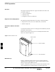
BTS Preparation Overview The purpose of this procedure is to prepare the BTS for the ATP. This procedure consists of: 1. Solar Cover Removal 2. BTS Power Up 3. Diagnostic Access Cover Removal Required Tools and Equipment The following tools and materials are necessary to do this procedure: Torque driver wrench, 1/4–in.
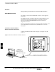
BTS Preparation – continued Figure 7-2: Location of AC Power Breakers Inside Primary Surge Suppressor AC POWER BREAKER CARRIER 2 AC POWER BREAKER CARRIER 3 AC POWER BREAKER CARRIER 4 AC POWER BREAKER CARRIER 1 MAIN INPUT BREAKER Figure 7-3: Location of AC and DC Power Breakers 7 AC POWER BREAKER DC POWER BREAKER JAN 2002 SC 300 1X BTS Hardware Installation, ATP, and FRU Procedures DRAFT 7-3
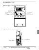
BTS Preparation – continued Procedure to Remove Diagnostic Access Cover NOTE The screws are captivated. Do not attempt to remove them from the cover. Table 7-1: Procedure for Removing Diagnostic Access Cover Step Action 1 Using a T20 Torx tamper bit, loosen the two tamper resistant M4 screws holding the cover. See Figure 7-4. 2 Gently tap the cover to loosen if required. 3 Remove the cover and set inside a secure place.
BTS Preparation – continued Figure 7-5: Detail Location of the Diagnostic Access Area 7 JAN 2002 SC 300 1X BTS Hardware Installation, ATP, and FRU Procedures DRAFT 7-5
Connect LMF to BTS Overview This procedure gives instructions to connect the LMF to the BTS. LMF to BTS Connection The LMF is connected to the MMI/LMF connector on the diagnostic access area. The LMF serial port, or PCMCIA (Personal Computer Memory Card International Association) Serial Adapter provides the connection between the LMF and the MMI/LMF connector located on the diagnostic access area.
Connect LMF to BTS – continued Procedure to Connect LMF to BTS via Ethernet Connection You can connect the LMF to the BTS via an Ethernet connection. Depending upon site configuration, you can use an Ethernet connection with or without an Ethernet hub. For example, if your BTS is mounted on a pole and there is no power connection available for the Ethernet hub, then you can connect to the BTS via a RJ45 crossover cable or a MMI to LAN crossover adapter.
Connect LMF to BTS – continued Figure 7-8: Ethernet Crossover Cable and Adapter Wiring RJ45 ETHERNET CABLE CROSSOVER CONFIGURATION TX+ BLUE 1 1 ORANGE 2 TX– 3 RX+ BLACK RX– RED GREEN 15–PIN D–SUB RJ–45 TX+ BLUE 2 4 3 5 TX– YELLOW 6 MMI/LAN ADAPTER CROSSOVER CONFIGURATION 6 15 4 12 1 ORANGE 2 RX+ BLACK RX– YELLOW 3 6 RED 4 5 GREEN BROWN 7 GRAY 5 BROWN 8 GRAY 7 8 Figure 7-9: Ethernet BTS to LMF Connection Using Crossover Cable or Adapter NOTE: YOU MUST CONFIGURE EITHER THE R
Connect LMF to BTS – continued MMI/LMF serial connector information Refer to Figure 7-10 and Table 7-2 for information for the 15–pin MMI/LMF connector.
Connect Test Equipment to BTS Overview The following test equipment setup applies to the BTS Acceptance Test Procedure (ATP). The SC 300 BTS supports the following test sets for IS95 A/B testing: 1. Advantest R3465 with R3561 Signal Generator. 2. Motorola CyberTest 3. HP 8921A (for 800 MHz testing only) 4. Aglient 8935 Series E6380A (formally HP8935) The 1X SC 300 BTS supports the following test sets for CDMA2000 1X testing: 1. Advantest R3267 with R3562 Signal Generator 2.
Connect Test Equipment to BTS – continued NOTE In the following procedure and illustrations, typical DIP switch positions and/or configurations are shown. If required, refer to the test equipment OEM user manuals for additional information. Procedure to Connect Advantest R3465 to BTS Follow the procedure in Table 7-3 to connect the Advantest R3465 to the BTS. Refer to Figure 7-11.
Connect Test Equipment to BTS – continued Figure 7-11: Communications Test Set Timing Signal Detail (Advantest R3465) BTS DIAGNOSTIC ACCESS AREA CONNECTIONS DEPICTED BY HEAVY BOLD LINES ARE STATIONARY AND SHOULD REMAIN INSTALLED DURING TEST EQUIPMENT TRANSPORT FROM SITE TO SITE. 2 SECOND REFERENCE 19.
Connect Test Equipment to BTS – continued Procedure to Connect Advantest R3267 to BTS Use the procedures in Table 7-4 to connect the Advantest R3267 to the BTS. Refer to Figure 7-12. NOTE The Advantest R3267 test set is used for 1X system testing. Table 7-4: Procedure to Connect Advantest R3267 to the BTS Step Action 1 Connect an SMA/BNC coax cable between the following points: – BNC on the MOD TIMEBASE IN port on the front panel of the Advantest R3562 Test Source.
Connect Test Equipment to BTS – continued Figure 7-12: R3267 Communications Test Set Timing Signal Detail BTS DIAGNOSTIC ACCESS AREA CONNECTIONS DEPICTED BY HEAVY BOLD LINES ARE STATIONARY AND SHOULD REMAIN INSTALLED DURING TEST EQUIPMENT TRANSPORT FROM SITE TO SITE. 2 SECOND REFERENCE 19.
Connect Test Equipment to BTS – continued Procedure to Connect the Motorola CyberTest, HP 8935, and HP 8921 to BTS Figure 7-13: Communications Test Set Timing Signal Detail (CyberTest, HP 8935, and HP 8921) BTS DIAGNOSTIC ACCESS AREA COMMUNICATIONS TEST SET MOTOROLA CYBERTEST SYNC MONITOR EVEN SEC TICK PULSE REFERENCE FROM DIAGNOSTIC ACCESS AREA FREQ MONITOR 19.
Connect Test Equipment to BTS – continued Procedure to Connect the Agilent E4406A/E4432B to BTS Agilent E4406A/E4432B test equipment interconnection To provide proper operation during testing when both units are required, the 10 MHz reference signal from the E4406A transmitter test set must be provided to the E4432B signal generator. Connect a BNC (M)–BNC (M) cable from the E4406A 10 MHz OUT (SWITCHED) connector to the E4432B 10MHz IN connector as shown in Figure 7-14.
Connect Test Equipment to BTS – continued Figure 7-15: Agilent E4406A/E4432B Communications Test Set Timing Signal Detail BTS DIAGNOSTIC ACCESS AREA CONNECTIONS DEPICTED BY HEAVY BOLD LINES ARE STATIONARY AND SHOULD REMAIN INSTALLED DURING TEST EQUIPMENT TRANSPORT FROM SITE TO SITE. Agilent E4432B (Top) and E4406A (Bottom) 2 SECOND REFERENCE 19.
Connect Test Set and Power Meter to LMF Procedure to Connect the Communication Test Set and Power Meter to the LMF Use the following procedure in Table 7-5 to connect the communication test set to the power meter and to the LMF. Refer to Figure 7-16. Table 7-5: Procedure to Connect the Communication Test Set and Power Meter to the LMF Step Action 1 Connect the RS232–IEEE488 converter serial cable between the COM1 port of the LMF and the RS232 port of the RS232–IEEE488 converter.
Connect Test Set and Power Meter to LMF – continued RS232 Cable Configuration One National Instruments GPIB–232–CT with Motorola CGDSEDN04X RS232 serial cable or equivalent is used to interface the LMF to the test equipment. A Standard RS–232 cable can be used with the following modifications: Pin 8 (CTS) does not have to be jumpered/shorted to the others as it is a driver output. The DTR is already a driver output signal. The other pins are to receivers.
BTS Configuration Objective The objective of this procedure is to configure the BTS and establish communication sessions between the LMF and BTS. This procedure consists of: 1. Creating a named hyperterminal connection for MMI communication 2. Establishing an MMI communication session 3. Verify and set IP address 4. Programming customer operating channel 5. Verifying BTS synchronization mode 6. Verifying DPLL tracking 7.
BTS Configuration – continued Table 7-6: Procedure to Create a Named HyperTerminal Connection for MMI Communication Step 3 Action When the Connection Description box opens: – Type a name for the connection being defined (e.g., MMI Session) in the Name: window, – Highlight any icon preferred for the named connection in the Icon: chooser window, and – Click OK.
BTS Configuration – continued Procedure to Establish an MMI Communication Session For those procedures which require MMI communication between the CDMA LMF and the BTS, follow the procedures in Table 7-7 to initiate the communication session. NOTE If an LMF session is in progress, logout of the LMF prior to establishing an MMI communication session. Refer to steps 1 and 2 of the “Remove LMF” procedure in Table 7-54.
BTS Configuration – continued Procedure to Set IP Address You must set an IP address on the unit before you can begin an LMF Ethernet (LAN) session. Follow the instructions in Table 7-8 to set the IP address. Table 7-8: Procedure to Set IP Address Step 1 Action Enter the following command to check the ethernet IP address: sc300>ether getip Observe the following typical response (if the IP address was not set): COMMAND ACCEPTED: ether getip Current IP ADDRESS: 0.0.0.
BTS Configuration – continued Table 7-8: Procedure to Set IP Address Step 6 Action Enter the following command at the sc300> prompt: sc300>ether setgw 128.0.0.2 The system will display the following output: COMMAND ACCEPTED: ether setgw 128.0.0.2 ”128” ”0” ”0” ”2” THESE ARE THE BYTES READ IN: 128.0.0.2 SETTING GW: 128.0.0.2 Completed flashing of Gateway address CONFIRM NEW GW: 128.0.0.2 New parameters will take affect after next reset.
BTS Configuration – continued Updating Default Channel Setting to Customer Operating Channel A non–volatile database containing the default channel and default power level of the site must be programmed. The default channel is the customer operating channel for this site. The default power level must be set to –50 dBm which will be overwritten by the MM/OMCR when the site comes on–line. It is imperative that the customer frequency be programmed into this database.
BTS Configuration – continued Synchronization Background GPS GPS is typically used as the primary timing reference for CDMA BTSs. In applications where RGPS is used, the BTS is said to be synchronous with CDMA system time. The RGPS provides a 1 Pulse Per Second timing reference and Time Of Day information to allow the BTS to synchronize to CDMA system time. HSO A High Stability Oscillator (HSO) within the BTS provides a backup timing reference in the event of a GPS outage.
BTS Configuration – continued sources (RGPS or HSO). Under normal operating conditions, the acquisition states last about 5 minutes. The TK state is the DPLL tracking state and is entered at the end of the acquisition states. The TK state is required for performing ATP. Procedure to Verify and Change BTS Synchronization Mode The Sync button in the Diagnostic Access Area is used to toggle the RGPS or HSO as the primary timing reference for the BTS.
BTS Configuration – continued Procedure to Verify DPLL Tracking (RGPS/HSO) The DPLL within the BTS must be tracking either RGPS or HSO in order to perform ATP. Use the procedure in Table 7-11 to verify DPLL tracking. Table 7-11: Procedure to Verify DPLL Tracking Step Action 1 If an MMI session was established, proceed to step 6. If no MMI session is running, proceed to step 2. 2 Connect the MMI/LMF. 3 Open an MMI Communication session.
BTS Configuration – continued Table 7-11: Procedure to Verify DPLL Tracking Step Action 9 Issue the dpll_status command to display the current state of the DPLL. Observe the following typical response: Current source set to: GPS reference DPLL control task state: DPLL track. DPLL status (not valid if using even sec src): c:0000 off: –8639450,6736579,7204904 TK (Note: This must say TK.
BTS Configuration – continued Table 7-12: Procedure to Verify Default Startup Coordinates Step Action 6 Issue the dpll_status command to display the current state of the DPLL. Verify that the DPLL has a ”Current source set to” of GPS reference and a ”DPLL control task state” of DPLL track. The DPLL must be tracking GPS in order to complete this procedure. 7 * IMPORTANT The values for longitude and latitude in response to the gps_status command are given in units of milli–arcseconds.
BTS Configuration – continued Procedure to Set Frame ID for Multi–Unit Logical BTS Configuration Do the following procedure in Table 7-13 to setup the hardware for a multi–unit logical BTS configuration. Table 7-13: Procedure to Set Frame ID for Multi–Unit Logical BTS Configuration Step Action 1 Establish an MMI session with the BTS. Refer to Table 7-7.
BTS Software Objective This objective of this procedure is to: 1. Install the LMF program. 2. Create a site specific BTS directory. 3. Start the LMF. 4. Login to the BTS 5. Update the BTS–specific CDF file. 6. Download and enable the MAWI Install the LMF Program and BTS Binaries Install the LMF and BTS binaries on the PC to be used if they are not already installed. Refer to the CDMA LMF Operator’s Guide, 68P64114A78 for the installation procedure.
BTS Software – continued Table 7-15: Procedure to Start the LMF and Login to the BTS Step Action 1 Click on the LMF desktop icon. The LMF window should appear. 2 Click on the Login tab if it is not already displayed. 3 Double–click on CDMA in the Available Base Stations pick list if the list of available BTSs is not displayed. 4 Click on the desired BTS. 5 Is all of the information in the Serial Login tab and Equipage Information box list correct? – If YES, go to step 7. – If NO, go to step 6.
BTS Software – continued Table 7-16: Procedure to Update BTS–Specific CDF File Device Load Version Step Action 3 Select CDMA. 4 Select the BTS number from the list of available base stations. 5 Select the radio button next to the desired version number. 6 Click on the Save button. A pop–up message will appear indicating that “This action may take a few seconds.” Click on the OK button. 7 A pop–up message will appear indicating that the NextLoad file has been updated.
BTS Software – continued Table 7-17: Procedure to Download/Enable MAWI Step Action 4 Click on the MAWI and select Device>Download>Code Data. A status report is displayed that confirms the change in device status. Click OK to close status window. 5 Click on the MAWI and select Device>Enable to enable the MAWI. The MAWI changes to green (INS–ACT test mode). NOTE The LMF may fail this step.
BTS Software – continued System Status LED States Table 7-18 lists all of the possible system status LED states. Table 7-18: System Status LED States System Status LED Status Indication Steady Green INS_ACT or INS_SBY , no alarms Slow Flashing Red/Green (0.2s Red, 1.4s Green) INS_ACT or INS_SBY w/alarms(s) Fast Flashing Green/Off (0.2s Green, 0.2s Off) OOS_RAM with no alarms Fast Flashing Red/Green (0.2s Red, 0.2s Green) OOS_RAM with alarms(s) Slow Flashing Green/Off (0.2s Green, 1.
Verify and Set Span Line Settings Objective The following procedure is to verify and configure the BTS Span line interface for T–1 or E–1 configurations. Span Line Settings The following are the span line settings for the BTS span line interface. Span A: Primary span Span B: Downstream span used for daisy–chaining. Procedure to Verify and Set Span Line Settings Use the procedure in Table 7-19 to verify and set (if necessary) the span line settings.
Verify and Set Span Line Settings – continued Table 7-19: Procedure to Verify and Set Span Line Settings Step Action 5 If the span line settings are not the same for spans A and B, then enter the SPAN_CONFIG command for span A. Refer to the SPAN_CONFIG parameters in Table 7-20. SC300>span_config The SPAN_CONFIG parameters shown below are an example and may not be applicable to your configuration.
Verify and Set Span Line Settings – continued SPAN_CONFIG Parameters The following parameters in Table 7-20 are for the SPAN_CONFIG command.
GPIB Addresses Introduction Use the following procedures to verify and/or change the GPIB addresses of the applicable test equipment. GPIB addresses can range from 1 through 30. The LMF will accept any address in that range, but the numbers in the GPIB address boxes must match the addresses of the test equipment. Motorola recommends that you use 1 for a CDMA signal generator, 13 for a power meter, and 18 for a CDMA analyzer.
GPIB Addresses – continued Figure 7-18: Gigatronics 8541C Power Meter Detail 1 MENU ENTER ARROW KEYS Verify and Set Motorola CyberTest GPIB Address Follow the steps in Table 7-22 to verify and, if necessary, change the GPIB address on the Motorola CyberTest. Changing the GPIB address requires the following items: Motorola CyberTest communications analyzer. Computer running Windows 3.1/Windows 95. Motorola CyberTAME software program “TAME”.
GPIB Addresses – continued Verify and Set HP8935 Test Set GPIB Address Follow the procedure in Table 7-23 to verify and, if necessary, change the HP8935 GPIB address. Table 7-23: Verify and/or Change HP8935 GPIB Address Step 1 Action * IMPORTANT The HP I/O configuration MUST be set to Talk & Listen, or NO device on the GPIB bus will be accessible (if necessary, consult test equipment OEM documentation for additional information).
GPIB Addresses – continued Verify and Set the HP8921A and HP83236A/B GPIB Addresses Follow the procedure in Table 7-24 to verify and, if necessary, change the HP8921A/HP83236A GPIB addresses. Table 7-24: Verify and/or Change HP8921A and HP83236A GPIB Addresses Step Action 1 To verify that the GPIB addresses are set correctly, press Shift and LOCAL on the HP8921A (refer to Figure 7-20). The current HP–IB address is displayed at the top of the screen. NOTE HP–IB is the same as GPIB.
GPIB Addresses – continued Verify and Set Advantest R3465 GPIB Address Table 7-25 describes the steps to verify and, if necessary, change the GPIB address for the Advantest R3465. Table 7-25: Verify and/or Change Advantest R3465 GPIB Address Step Action 1 Perform the following procedure to verify that the GPIB address is set correctly: – Press SHIFT then PRESET (see Figure 7-21). – Press LCL. – Press the GPIB and Others CRT menu key to view the current address.
GPIB Addresses – continued RS232 GPIB Interface Box Ensure that the RS232 GPIB interface box dip switches are set as shown in Figure 7-22. Figure 7-22: RS232 GPIB Interface Box DIP SWITCH SETTINGS S MODE DATA FORMAT BAUD RATE ON GPIB ADRS G MODE RS232–GPIB INTERFACE BOX Verify and Set Advantest R3267 GPIB Address Perform the procedure in Table 7-26 and refer to Figure 7-23 to verify and, if necessary, change the Advantest R3267 spectrum analyzer GPIB address.
GPIB Addresses – continued Table 7-26: Verify and Change Advantest R3267 GPIB Address Step 3b Action Enter 18 on the keypad in the ENTRY section of the instrument front panel. – Characters typed on the keypad will replace the address displayed in the GPIB Address entry window. NOTE To correct an entry, press the BS (backspace) key at the lower right of the keypad to delete one character at a time. 3c Press the ENTR key to the lower right of the keypad to enter the address.
GPIB Addresses – continued Verify and Set Advantest R3562 Signal Generator GPIB Address Set the GP–IP ADDRESS switch on the rear of the Advantest R3562 signal generator to address 1 as shown in Figure 7-24.
GPIB Addresses – continued Table 7-27: Verify and Change Agilent E4406A GPIB Address Step Action 3b On the front panel Data Entry keypad, enter the communications system analyzer GPIB address of 18. – The GPIB Address label will change to Enter. – Digits entered with the keypad will replace the current GPIB address in the display. NOTE To correct an entry, press the Bk Sp key at the upper right of the keypad to delete one character at a time.
GPIB Addresses – continued Verify and Set Agilent E4432B Signal Generator GPIB Address Refer to Figure 7-26 and follow the procedure in Table 7-28 to verify and, if necessary, change the Agilent E4432B GPIB address. Table 7-28: Verify and Change Agilent E4432B GPIB Address Step Action 1 In the MENUS section of the instrument front panel, press the Utility key. – The softkey labels displayed on the right side of the instrument screen will change.
GPIB Addresses – continued Figure 7-26: Setting Agilent E4432B GPIB Address Active Entry Area Softkey Label Display Area Utility Key Softkey Buttons Numeric Keypad Backspace Key 7 7-50 SC 300 1X BTS Hardware Installation, ATP, and FRU Procedures DRAFT JAN 2002
Test Equipment Calibration Background CAUTION To prevent damage to the test equipment, all Microcell transmit (TX) tests must be made using the 30 dB attenuator. Proper test equipment calibration ensures that the test equipment and associated test cables do not introduce measurement errors, and that measurements are correct. NOTE If the test set being used to interface with the BTS has been calibrated and maintained as a set, this procedure does not need to be performed.
Test Equipment Calibration – continued Procedure to Calibrate Test Equipment The calibrate test equipment function zeros the power measurement level of the test equipment item that is to be used for TX calibration and audit. If both a power meter and an analyzer are connected, only the power meter is zeroed. Use the Calibrate Test Equipment menu item from the Util menu to calibrate test equipment. The test equipment must be selected before calibration can begin.
Test Equipment Calibration – continued Procedure to Calibrate R3465 Test Set Follow the steps inTable 7-30 to configure and calibrate the R3465 communication test set. Table 7-30: Procedure to Calibrate R3465 Step 1 Action * IMPORTANT – Perform this calibration only after the analyzer has warmed–up and stabilized for a minimum of 60 minutes. Test equipment warm–up may vary depending on operating environment or initial temperature of unit upon turn–on.
Test Equipment Calibration – continued Procedure to Calibrate Agilent E4406A Refer to Figure 7-27 and follow the procedure in Table 7-32 to perform the Agilent E4406A self–alignment (calibration). Table 7-32: Perform Agilent E4406A Self–alignment (Calibration) Step Action 1 In the SYSTEM section of the instrument front panel, press the System key. – The softkey labels displayed on the right side of the instrument screen will change.
Test Equipment Calibration – continued Procedure to Setup Advantest R3465 Test Equipment Follow the steps outlined in Table 7-33 (for Advantest R3465) or Table 7-34 (for Advantest R3267) to set up test equipment prior to performing ATP tests. IMPORTANT * LMF based measurements factor in cable and attenuator loss between the BTS and test equipment. No additional attenuation can be inserted as the additional losses would not be factored in.
Test Equipment Calibration – continued Procedure to Setup Advantest R3267 Test Equipment Table 7-34: Procedure to Setup Advantest R3267 Test Equipment Step Action 1 If you have not already done so, interface the CDMA LMF computer to the BTS and login to the BTS. 2 Perform the following steps for the manual test procedure for Automated TX verification. Set up the communication test set by inserting the Automatic TX test PCMCIA card into the Advantest PCMCIA card reader slot A. (software revision 0.0.0.
Test Equipment Selection Objective The objective of this procedure is to select the test equipment used for BTS testing. The LMF must select the test equipment before it is used for BTS testing. Prerequisites The following are prerequisites for test equipment selection: 1. Test equipment to be used has been connected as shown in Figure 7-16. 2. Power for the test equipment and GPIB box has been turned on. 3. LMF has been started (do not have to be logged in to the BTS).
Test Equipment Selection – continued Selecting Test Equipment Automatically or Manually Use LMF Options from the Tools>Options menu list to select test equipment automatically (using the autodetect feature) or manually. A Serial Connection and a Network Connection tab are provided for test equipment selection. The Serial Connection tab is used when the test equipment items are connected directly to the LMF computer via a GPIB box (normal setup).
Test Equipment Selection – continued Procedure to Automatically Select Test Equipment in a Serial Connection Tab When using the auto-detection feature to select test equipment, the LMF examines which test equipment items are actually communicating with the LMF. Follow the procedure in Table 7-37 to use the auto-detect feature. Table 7-37: Procedure to Select Test Equipment Using Auto-Detect Step Action 1 Select Tools>Options. The LMF Options window appears.
Power Meter Calibration Objective This procedure calibrates the power meter that will be used for cable calibration and BTS testing. Prerequisites The following are prerequisites for power meter calibration: 1. The power meter is connected. Refer to Figure 7-16 in the “Test Equipment Selection” procedure. 2. Test equipment has been selected. Procedure to Calibrate the Power Meter Follow the steps in Table 7-38 to calibrate the power meter.
Test Cable Calibration Background Proper test equipment setup ensures that all measurements are correct, and that test equipment and associated test cables do not introduce measurement errors. Motorola recommends repeating cable calibration prior to testing at each BTS site. If not already done so, this procedure needs to be performed prior to beginning the ATP.
Test Cable Calibration – continued Procedure to do an Automated Cable Calibration This procedure calibrates the cables that will be used for BTS testing. Follow the steps in Table 7-39 to calibrate the test cables. Refer to Figure 7-28. Prerequisites 1. Test equipment has been connected as shown in Figure 7-16. 2. Power for the test equipment and GPIB box has been turned on. 3. LMF has been started and BTS has been logged into. 4. Inspect and verify the TX and RX antenna cabling for your BTS.
Test Cable Calibration – continued Figure 7-28: Cable Calibration Test Setup (Motorola CyberTest, HP 8935, HP 8921, and Advantest R3465) SUPPORTED TEST SETS CALIBRATION SET UP Motorola CyberTest A. SHORT CABLE CAL ÎÎÎÎ ÎÎÎÎÏ ANT IN SHORT CABLE TEST SET RF GEN OUT Note: The Directional Coupler is not used with the Cybertest Test Set. The TX cable is connected directly to the Cybertest Test Set. B.
Test Cable Calibration – continued Figure 7-29: Cable Calibration Test Setup (Advantest R3267 and Agilent E4406A) CALIBRATION SET UP SUPPORTED TEST SETS A. SHORT CABLE CAL Agilent E4406A with E4432B Signal Generator SHORT CABLE TEST SET B. RX TEST SETUP N–N FEMALE ADAPTER RX CABLE SHORT CABLE TEST SET Advantest Model R3267 with R3562 Signal Generator ADVANTEST R3267 SPECTRUM ANALYZER 100Hz – 8GHz C.
Create CAL File Objective Use this procedure to create a CAL file for the Calibration audit. You must do this procedure before the RF path audit. Background The Create CAL File function gets the BLO data from the MAWI and creates/updates the CAL file for the BTS. If a CAL file does not exist, a new one is created. If a CAL file already exists, it is updated.
Create CAL File – continued Procedure to Create a CAL File Use the following procedure in Table 7-40 to create a CAL file. Table 7-40: Procedure to Create a CAL File Step Action 1 Log on to the BTS if you have not already done so. 2 Select the MAWI. 3 Click on the Device menu. 4 Click on the Create Cal File menu item. The status report window displays the results of the action. 5 Click OK. NOTE The bts–#.cal is located in the wlmf\cdma\bts–# folder (where # is the number of the BTS).
Acceptance Tests Overview This chapter describes the various TX and RX acceptance tests. TX Test Objective The following tests will verify the TX antenna path. Output power control will also be verified. All tests will be performed using the power meter and communication test set. Measurements will be via the Antenna B connectors. NOTE You must remove the antenna cables before you perform the ATP. The BTS is keyed up to generate a CDMA carrier at 31 dBm.
Acceptance Tests – continued CDMA carrier frequency verification You will verify the frequency of the transmitted CDMA carrier signal to be within 0.05 ppm. Code domain power noise, pilot power, and total power You will verify that the code domain noise floor of all unused Walsh codes within the CDMA spectrum measures < –27 dB (with respect to total power). Pilot power will be verified to measure –7.04 dB +/–0.5 dB (with respect to standard test patterns).
Subscriber Unit (SU) Test and Setup Objective The following procedure is to test and verify the operation of the Subscriber Unit (SU). This procedure also contains instructions to program the NAM parameters into the SU prior to operation. Background The integral Subscriber Unit (SU) provides a controlled method of terminating calls within the local BTS for diagnostic purposes.
Subscriber Unit (SU) Test and Setup – continued Table 7-41: Procedure to Test and Verify the Subscriber Unit Step 7 Action Enter the following command at the sc300’x–1> prompt to view the ESN number of the SU and the CAMPS version: su version The system will display the following output. Note that the ESN numbers will be different, but everything else will remain as shown below.
Subscriber Unit (SU) Test and Setup – continued Procedure to Program SU NAM Parameters Follow the instructions in Table 7-42 to program the SU NAM parameters.
Subscriber Unit (SU) Test and Setup – continued Table 7-42: Procedure to Program the SU NAM Parameters Step Action 6 Enter the following command at the sc300’x–1> prompt to program the System ID: su nam sid 7 Enter the following command at the sc300’x–1> prompt to program the Mobile Country Code (MCC) and IMSI 11&12 (MNC) code: su nam imsi For example, if the MCC code is “11” and the MNC code is “23,” you would enter: su nam imsi 1123 8 Enter the following command at the sc3
CDMA Operating Frequency Programming Information – North American Cellular Bands Objective The following tables show each of the valid operating channels for North American PCS Bands and their corresponding transmit and receive frequencies. 1900 MHz PCS Channels Figure 7-30 shows the valid channels for the North American PCS 1900 MHz frequency spectrum. Figure 7-30: North America PCS Frequency Spectrum (CDMA Allocation) FREQ (MHz) RX TX 1851.25 1931.25 CHANNEL 25 A 275 ÉÉÉ ÉÉÉ ÉÉÉ ÉÉÉ 1863.75 1943.
CDMA Operating Frequency Programming Information – North American Cellular Bands – continued Calculating 1900 MHz Center Frequencies Table 7-43 shows selected 1900 MHz CDMA candidate operating channels, listed in both decimal and hexadecimal, and the corresponding transmit, and receive frequencies. Center frequencies (in MHz) for channels not shown in the table may be calculated as follows: TX = 1930 + 0.05 * Channel# Example: Channel 262 TX = 1930 + 0.05*262 = 1943.
CDMA Operating Frequency Programming Information – North American Cellular Bands – continued Table 7-43: 1900 MHz TX and RX Frequency vs. Channel Channel Number Decimal Hex 600 0258 625 0271 650 028A 675 02A3 700 02BC 725 02D5 750 02EE 775 0307 800 0320 825 0339 850 0352 875 036B 900 0384 925 039D 950 03B6 975 03CF 1000 03E8 1025 0401 1050 041A 1075 0433 1100 044C 1125 0465 1150 047E 1175 0497 Transmit Frequency (MHz) Center Frequency 1960.00 1961.25 1962.50 1963.75 1965.00 1966.25 1967.50 1968.75 1970.
CDMA Operating Frequency Programming Information – North American Cellular Bands – continued 800 MHz CDMA Channels Figure 7-31 shows the valid channels for the North American cellular telephone frequency spectrum. OVERALL WIRELINE (B) BANDS ÉÉ ÉÉ ËË ËË 848.970 893.970 777 739 ËËË ËËË ËËË ËËË 799 891.480 891.510 846.480 846.510 716 717 694 ÉÉ ÉÉ ÉÉ ÉÉ 689 844.980 845.010 889.980 890.010 OVERALL NON–WIRELINE (A) BANDS 644 356 ËËË ËËË ËËË ËËË ËËË ËËË ËËË ËËË 666 667 879.990 880.020 834.
CDMA Operating Frequency Programming Information – North American Cellular Bands – continued Table 7-44: 800 MHz TX and RX Frequency vs. Channel Channel Number Decimal Hex Transmit Frequency (MHz) Center Frequency Receive Frequency (MHz) Center Frequency 75 004B 872.2500 827.2500 100 0064 873.0000 828.0000 125 007D 873.7500 828.7500 150 0096 874.5000 829.5000 175 00AF 875.2500 830.2500 200 00C8 876.0000 831.0000 225 00E1 876.7500 831.7500 250 00FA 877.5000 832.
TX Acceptance Tests Objective Refer to Table 7-45 to perform a TX ATP test. This procedure assumes that the site specific CDF file is in the wlmf\cdma\bts–# folder. The ALL TX list performs the following ATP tests: 1. TX Mask 2. Rho 3. Pilot Time Offset 4. Code Domain Power Prerequisites You must successfully complete all the procedures outlined in previous chapters before you attempt to run an ATP.
TX Acceptance Tests – continued Table 7-46: Procedure to Run TX Test Using Backup Synchronization Step Action 5 At the MMI prompt, enter dpll_info and verify that GPS and HSO are good reference sources. Observe the following typical response.
TX Acceptance Tests – continued Table 7-46: Procedure to Run TX Test Using Backup Synchronization Step Action 13 If logged into the BTS with the LMF, then logout. 14 Open an MMI Communication session. 15 Enter the status command to verify that the BTS is in OOS_RAM status. 16 Enter the sndtype 0xa178 command to simulate an LMF connection. 17 Enter the gps_rx_debug nosats off command at the MMI prompt to disable the simulation of the GPS losing tracked satellites.
TX Acceptance Tests – continued Figure 7-32: TX ATP Setup (CyberTest, HP 8935 and Advantest R3465) MICROCELL UNIT NOTE: THE DOTTED LINES REPRESENT THAT EITHER TX RF TEST CABLE CONNECTS TO BOTH COMMUNICATIONS TEST SET AND POWER METER ANTENNA B COMMUNICATIONS TEST SET MOTOROLA CYBERTEST ÎÎÎ ÎÎÎÏ 30DB IN-LINE ATTENUATOR RF IN/OUT AGILENT 8935 SERIES E6380A (FORMERLY HP 8935) ÁÁ Á ÁÁ Á RF IN/OUT ADVANTEST MODEL R3465 POWER METER: GIGATRONICS 8541C OR HP 437B 7 INPUT 50–OHM TRANSMIT RF TEST CABLE P
TX Acceptance Tests – continued Figure 7-33: TX ATP Setup (HP 8921A) MICROCELL UNIT NOTE: THE DOTTED LINES REPRESENT THAT EITHER TX RF TEST CABLE CONNECTS TO BOTH COMMUNICATIONS TEST SET AND POWER METER ANTENNA B COMMUNICATIONS TEST SET HEWLETT–PACKARD MODEL HP 8921A W/PCS INTERFACE (FOR 1700 AND 1900 MHz) 30DB IN-LINE ATTENUATOR RF IN/OUT HEWLETT–PACKARD MODEL HP 8921A (FOR 800 MHz) 7 RF IN/OUT POWER METER: GIGATRONICS 8541C OR HP 437B TRANSMIT RF TEST CABLE POWER SENSOR 7-82 SC 300 1X BTS Har
TX Acceptance Tests – continued Figure 7-34: TX ATP Setup (Advantest R3267 and Agilent E4406A) NOTE: THE DOTTED LINES REPRESENT THAT EITHER TX RF TEST CABLE CONNECTS TO BOTH COMMUNICATIONS TEST SET AND POWER METER AGILENT E4432B (TOP) AND E4406A (BOTTOM) ANTENNA B ADVANTEST R3267 (TOP) AND R3562 (BOTTOM) ADVANTEST R3267 SPECTRUM ANALYZER 100Hz – 8GHz 30DB IN-LINE ATTENUATOR INPUT 50 OHM RF INPUT POWER METER ADVANTEST R3562 RECEIVER TEST SOURCE TRANSMIT RF TEST CABLE 7 POWER SENSOR JAN 2002 SC 3
RX Acceptance Tests Objective This procedure assumes that the site specific CDF file is in the wlmf\cdma\bts–# folder. Prerequisites You must successfully complete all the procedures outlined in previous chapters before you attempt to run an ATP. Procedure to Run RX ATP Test Refer to Table 7-47 to perform an RX ATP test. This procedure assumes that the site specific CDF file is in the wlmf\cdma\bts–# folder.
RX Acceptance Tests – continued Figure 7-35: RX ATP Setup (CyberTest, HP 8935, and Advantest R3465) MICROCELL UNIT ANTENNA B (MAIN) ANTENNA A (DIVERSITY) COMMUNICATIONS TEST SET MOTOROLA CYBERTEST ÎÎÎÎ ÏÏ ÎÎÎÎ AGILENT 8935 SERIES E6380A (FORMERLY HP 8935) RF GEN OUT ÁÁ ÁÁ ADVANTEST MODEL R3465 RECEIVE RF TEST CABLE 7 RF IN/OUT RF OUT JAN 2002 SC 300 1X BTS Hardware Installation, ATP, and FRU Procedures DRAFT 7-85
RX Acceptance Tests – continued Figure 7-36: RX ATP Setup (HP 8921A) MICROCELL UNIT ANTENNA B (MAIN) COMMUNICATIONS TEST SET HEWLETT–PACKARD MODEL HP 8921A W/PCS INTERFACE (FOR 1700 AND 1900 MHz) ANTENNA A (DIVERSITY) RF OUT ONLY HEWLETT–PACKARD MODEL HP 8921A (FOR 800 MHz) RECEIVE RF TEST CABLE 7 RF IN/OUT 7-86 SC 300 1X BTS Hardware Installation, ATP, and FRU Procedures DRAFT JAN 2002
RX Acceptance Tests – continued Figure 7-37: RX ATP Setup (Advantest R3267 and Agilent E4406A) ANTENNA A (DIVERSITY) ANTENNA B (MAIN) ADVANTEST R3267 (TOP) AND R3562 (BOTTOM) ADVANTEST R3267 SPECTRUM ANALYZER 100Hz – 8GHz AGILENT E4432B (TOP) AND E4406A (BOTTOM) RF OUTPUT RECEIVE RF TEST CABLE ADVANTEST R3562 RECEIVER TEST SOURCE RF OUT 7 JAN 2002 SC 300 1X BTS Hardware Installation, ATP, and FRU Procedures DRAFT 7-87
Generate an ATP Report Background Each time an ATP test is run, an ATP report is updated to include the results of the most recent ATP tests if the Save Results button is used to close the status report window. The ATP report will not be updated if the status reports window is closed with use of the Dismiss button.
Copy LMF CAL File to CBSC Objective The following procedure is to copy the LMF CAL file to the CBSC after performing an ATP. Background After you perform the ATP you must move a copy of the CAL file for the BTS from the LMF to the CBSC. This is normally done by putting a copy of the CAL file on a floppy disk and then using the floppy disk to move the CAL file to the CBSC. Prerequisites A DOS formatted 1.44 MB 3 1/2–in. floppy disk is necessary to do this procedure.
Copy LMF CAL File to CBSC – continued Procedure to Copy CAL Files from Diskette to the CBSC Follow the procedures in Table 7-50 to copy CAL file from a diskette to the CBSC. Table 7-50: Procedure to Copy CAL Files from Diskette to the CBSC Step Action 1 Log in to the CBSC on the OMC–R Unix workstation using your account name and password. 2 Place your diskette containing calibration file(s) in the workstation diskette drive. 3 Type in eject –q and press the Enter key.
Prepare to Leave the Site Remove External Test Equipment Perform the procedure in Table 7-51 to disconnect the test equipment and prepare the BTS for active service. Table 7-51: Remove External Test Equipment Step Action 1 Disconnect all test equipment from the antenna connectors on the BTS. 2 Reconnect and visually inspect all antenna feed lines on the BTS. 3 Disconnect all test equipment from the diagnostic access area.
Prepare to Leave the Site – continued Table 7-53: Procedure to Bring BTS into Service Step Action 1 On the CDMA LMF, select the MAWI. 2 Click on Device from the menu bar. 3 Click on Enable from the Device menu. A status report window is displayed. 4 Click Cancel to close the transceiver parameters window, if applicable. 5 Click OK to close the status report window. The selected devices that successfully change to INS change color to green.
Prepare to Leave the Site – continued Replace Diagnostic Access Cover Use a T20 Torx tamper bit to tighten the two tamper–resistant M4 screws holding the cover. Torque to 10 in–lb. Refer to Figure 7-38. Figure 7-38: How To Replace The Diagnostic Access Cover SCREWS IN DIAGNOSTIC ACCESS COVER ARE CAPTIVE 7 Replace Solar Cover Replace the solar cover. Refer to the “Powering on Unit and Mounting the Solar Cover” procedure in Chapter 5.
Prepare to Leave the Site – continued Notes 7 7-94 SC 300 1X BTS Hardware Installation, ATP, and FRU Procedures DRAFT JAN 2002
Chapter 8: Field Replaceable Unit (FRU) Procedures Table of Contents JAN 2002 Field Replaceable Unit (FRU) Overview . . . . . . . . . . . . . . . . . . . . . . . . . . . . . . Overview . . . . . . . . . . . . . . . . . . . . . . . . . . . . . . . . . . . . . . . . . . . . . . . . List of FRUs . . . . . . . . . . . . . . . . . . . . . . . . . . . . . . . . . . . . . . . . . . . . . 8-1 8-1 8-1 Shut Down & Restoring BTS Signaling . . . . . . . . . . . . . . . . . . . . . . . . . . . . . . . Objective . .
Table of Contents – continued Notes 8 SC 300 1X BTS Hardware Installation, ATP, and FRU Procedures DRAFT JAN 2002
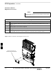
Field Replaceable Unit (FRU) Overview Overview The purpose of this chapter is to provide the Field Replaceable Unit (FRU) replacement procedures for the unit. Figure 8-1, Figure 8-2 and Figure 8-3 show the FRUs associated with the unit. List of FRUs The following is a list of FRUs for the unit: 1. Site I/O Junction Box with Primary Surge Suppressor – Kit T450AE 2. Site I/O Junction Box without Primary Surge Suppressor – Kit T450AA 3. RGPS Head – Kit T472AP 4. Short Duration Battery – Kit T348AE 5.
Field Replaceable Unit (FRU) Overview – continued Figure 8-2: Front and Back Solar Covers for MicroCell FRONT COVER BACK COVER Figure 8-3: Front and Back Fin Covers BACK COVER 8 FRONT COVER 8-2 SC 300 1X BTS Hardware Installation, ATP, and FRU Procedures DRAFT JAN 2002
Shut Down & Restoring BTS Signaling Objective The FRU procedures require the shut down of BTS signalling functions. Accessing the OMCR CLI window The commands to manipulate the BTS in the following replacement procedure must be entered via UNO or OMCR (Operations and Maintenance Center – Radio). IMPORTANT * Should there be any issues which affect CLI operations or the UNO/OMCR, this replacement procedure cannot be performed.
Shut Down & Restore BTS Signaling – continued IMPORTANT * The EDIT SECTOR REDIRECT or REDIRECT2 command does NOT affect calls in progress and will NOT move these calls to another sector/carrier. The command only prevents future calls from being originated on the targeted sector/carrier. If active call processing is still taking place in the target sector/carrier, it is advisable to wait for any active calls to terminate prior to disabling the sector.
Shut Down & Restore BTS Signaling – continued Table 8-2: Procedure to Shut Down Signaling Functions Step 3 Action NOTE This step edits the redirect parameters so that the Global Service Redirect Message broadcast on the paging channel redirects all subscribers away from the sector with the failed equipment and onto a different system.
Shut Down & Restore BTS Signaling – continued Table 8-2: Procedure to Shut Down Signaling Functions Step 4 Action View the status of the sector signaling redirect parameters to verify that the sector is ready for maintenance. omc–000000>display sector–– redirect Ensure that the values in the system display response match the values input in step 3 (see example below).
Shut Down & Restore BTS Signaling – continued Table 8-2: Procedure to Shut Down Signaling Functions Step 7 Action NOTE This step edits the REDIRECT2 parameters so that the Global Service Redirect Message broadcast on the paging channel redirects all subscribers away from the BTS with the failed equipment and onto a CDMA channel at a neighbor site. Enter the following command at the prompt: omc–000000> edit sector–redirect2! The system prompts you to enter each command parameter value one at a time.
Shut Down & Restore BTS Signaling – continued Table 8-2: Procedure to Shut Down Signaling Functions Step Action 9 View the existing congestion control parameters for all carriers equipped for the sector by entering the following command at the prompt: omc–000000>display sector–– congestconf Observe the following typical system display response: CARRIER (bts#–sector#–carrier#) ––––––––––––––––––––––– 300–1–4 10 SET ––– 1 NEWCALL ALARMFLAG ––––––––– ENABLE REG ALARMFLAG –––––––––– ENAB
Shut Down & Restore BTS Signaling – continued Table 8-2: Procedure to Shut Down Signaling Functions Step 12 Action Display the status of the MAWI at the BTS to verify the status of the MAWI (which CEs are INS_IDLE or INS_BUSY) by entering the following command at the prompt: omc–000000>status mawi–– add Observe the following typical system response: MAWI–300–1 00–05–24 15:10:31 omcr5 MM–5 M000109.
Shut Down & Restore BTS Signaling – continued Restore Signaling Operations Follow the steps in Table 8-3 to restore signaling operations to the site. Table 8-3: Procedure to Restore Signaling Operations Step Action 1 Open a CLI window. Refer to Table 8-1.
Shut Down & Restore BTS Signaling – continued Table 8-3: Procedure to Restore Signaling Operations Step 5 Action * IMPORTANT In this step, use the values recorded in step 2 of the shut down signaling functions table to answer the prompts for the EDIT SECTOR REDIRECT command; except for record type enter 2. NOTE This step shows the entry of initial standard values which is consistent with the original example; except record type must be 2. Your entries may be different.
Shut Down & Restore BTS Signaling – continued Table 8-3: Procedure to Restore Signaling Operations Step 7 Action View the congestion control parameters for all carriers equipped for the sector by entering the following command at the prompt: omc–000000>display sector–– congestconf Observe the following typical system display response: CARRIER (bts#–sector#–carrier#) ––––––––––––––––––––––– 300–1–4 8 SET ––– 1 NEWCALL ALARMFLAG ––––––––– ENABLE REG ALARMFLAG ––––––––– ENABLE AGG ALARMF
Shut Down & Restore BTS Signaling – continued Table 8-3: Procedure to Restore Signaling Operations Step 10 Action Display the status of the MAWI in the BTS by entering the following command at the prompt: omc–000000>status mawi–– add Observe the following typical system response for entry of: STATUS MAWI – 300 –1 ADD MAWI–300–1 00–05–24 15:10:31 omcr5 MM–5 M000109.
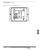
Site I/O Junction Box Replacement Procedure Objective The objective of this procedure is to replace the Site I/O junction box. System Impact/Considerations The removal of the failed Site I/O junction box will require system downtime. The BTS cannot report alarms without the Site I/O junction box. The other system level alarms are too numerous and outside the scope of this document.
Site I/O Junction Box Replacement Procedure – continued Remove the failed site I/O junction box Follow the steps in Table 8-5 to remove the failed Site I/O junction box. Table 8-5: Remove the Failed Site I/O Junction Box Step Action 1 Place the BTS out of service using the “Shut Down Signaling Functions” procedure shown in Table 8-2. 2 Using a T20 Torx tamper bit, remove the Solar Cover if one is present and locate the failed Site I/O junction box.
Site I/O Junction Box Replacement Procedure – continued Site I/O Junction Box Location Diagram Figure 8-4: Site I/O Junction Box Replacement NOTE: SU REMOVED FOR CLARITY DISCONNECT GROUND REMOVE TWO M6 CAPTIVE SCREWS SITE I/O JUNCTION BOX DISCONNECT SITE I/O CABLE FROM SITE I/O INTERFACE 8 8-16 SC 300 1X BTS Hardware Installation, ATP, and FRU Procedures DRAFT JAN 2002
Short Duration Battery Replacement Procedures Objective The objective of this procedure is to replace the short duration battery. Required Tools and Materials The following tools are required to remove the solar cover and install the new battery. Tools Attaching the battery to the unit requires: T20 Torx tamper bit, 1/4–in. hex T30 Torx tamper bit, 1/4–in. hex Torque driver wrench, 1/4–in.
Short Duration Battery Replacement Procedure – continued Table 8-8: Procedure to Remove the Failed Short Duration Battery Step Action 3 Turn the connector on the short duration battery cable counterclockwise to disconnect the cable from the unit. See NO TAG. An alarm will be generated. 4 Using a T30 Torx tamper bit remove the two screws that are holding the battery to the unit. See NO TAG. Install the replacement battery Follow the steps in Table 8-8 to install the replacement short duration battery.
Short Duration Battery Replacement Procedure – continued Figure 8-5: Short Duration Battery Replacement AC POWER BREAKER DC POWER BREAKER TURN COUNTERCLOCKWISE TO REMOVE CABLE REMOVE TWO SCREWS HOLDING BATTERY TO THE UNIT CABLE IS PART OF THE BATTERY ASSEMBLY 8 JAN 2002 SC 300 1X BTS Hardware Installation, ATP, and FRU Procedures DRAFT 8-19
Remote GPS Replacement Procedure Objective The objective of this procedure is to replace the RGPS head. Required Tools and Materials Replacement units One RGPS head with cable attached (Motorola Kit T472AP) is required to do this procedure. Procedure to Replace Remote GPS Before you begin Before you begin, enter the following information into the following replacement list table.
Remote GPS Replacement Procedures – continued Install the replacement RGPS head Follow the steps in Table 8-12 to install the replacement RGPS head. Refer to Figure 8-6. Table 8-12: Procedure to Install the Replacement RGPS Head Step Action 1 Connect the cable connector of the replacement RGPS head to the RGPS cable connector. Secure the connection by tightening the spinning connector flange. 2 Feed the cable slack into the RGPS head end of the mounting pipe/conduit.
Full Unit Replacement Procedures Objective The objective of this procedure is to replace a Microcell unit. See NO TAG. System Impact/Considerations The removal of the failed unit will require system downtime. Required Tools and Materials The following tools and materials are required to do this procedure: Tools The following tools are required to do this procedure: Torque driver wrench, 1/4–in. hex female drive, 0–10 N–M T20 TORX Tamper Bit, 1/4–in. hex T30 TORX Tamper Bit, 1/4–in.
Full Unit Replacement Procedures – continued Table 8-14: Procedure to Remove the Failed Unit Step Action 3 If DC power is being supplied to the unit or if battery backup is present, open (pull) the DC power breaker. The white collar on the breaker is visible when the breaker is opened. 4 If AC power is being supplied to the unit, open (pull) the AC power breaker. The white collar on the breaker is visible when the breaker is opened. 5 Turn the power off at the main power source (AC and/or DC).
Full Unit Replacement Procedures – continued Install the replacement unit Follow the steps in Table 8-15 to install the replacement unit. Table 8-15: Procedure to Install the New Unit Step Action 1 Attach the installation handles to the replacement unit. Refer to the “Attaching Installation Handles to Unit” procedure in Chapter 6. 2 Mount the replacement unit to the bracket. Refer to the “Attaching Unit to the Mounting Bracket” procedure in Chapter 6.
Full Unit Replacement Procedures – continued Figure 8-7: Unit Replacement REMOVE SCREWS USED TO HOLD UNIT ON BRACKET REMOVE SU CABLE (IF EQUIPPED) REMOVE SCREWS TO REMOVE SUBSCRIBER UNIT (IF EQUIPPED) REMOVE SCREWS TO REMOVE SITE I/O JUNCTION BOX OR SITE I/O CAP (IF EQUIPPED) REMOVE AC INPUT POWER CABLE REMOVE DC INPUT CABLE REMOVE MIB CABLES (OPTIONAL) REMOVE ANTENNA A CABLE REMOVE LOCK REMOVE ANTENNA B REMOVE SCREWS TO REMOVE SHORT DURATION BATTERY NOTE: REMOVE THE SITE I/O JUNCTION BOX (OR SITE I
Full Unit Replacement Procedures – continued Notes 8 8-26 SC 300 1X BTS Hardware Installation, ATP, and FRU Procedures DRAFT JAN 2002
A Appendix A: Outdoor Grounding Guidelines Overview Appendix Content Outdoor Grounding Guidelines Summary . . . . . . . . . . . . . . . . . . . . . . . . . . . . . Background . . . . . . . . . . . . . . . . . . . . . . . . . . . . . . . . . . . . . . . . . . . . . . Chassis Isolation . . . . . . . . . . . . . . . . . . . . . . . . . . . . . . . . . . . . . . . . . . Master Ground Plate . . . . . . . . . . . . . . . . . . . . . . . . . . . . . . . . . . . . . . . Main AC Power . . . . . . . . . . . . . . .
A Table of Contents – continued Notes SC 300 1X BTS Hardware Installation, ATP, and FRU Procedures DRAFT JAN 2002
Outdoor Grounding Guidelines Summary A Background This is a summary of the outdoor grounding guidelines. Outdoor installations should be based on this summary and site specific documentation. Motorola publication 68P81150E62 should also be followed to ground an antenna tower. This guideline assumes that auxiliary equipment is co–located at the installation site. All of the equipment referenced may not be present at every site.
A Outdoor Grounding Guidelines Summary – continued MGP at the antenna access point. The signal (center) conductor must be protected by a lightning arrestor. The lightning arrestor connects to the MGP at the same point as the ground conductor (shield) of the antenna cable. Chassis The ground stud of the BTS chassis connects to the MGP. T1 Span Lines The BTS can connect to two T1 span lines. For many applications the T1 cable is derived from an optical fiber interconnect.
Appendix B: Alarm List Appendix Content Release 15 Alarm List . . . . . . . . . . . . . . . . . . . . . . . . . . . . . . . . . . . . . . . . . . . . Objective . . . . . . . . . . . . . . . . . . . . . . . . . . . . . . . . . . . . . . . . . . . . . . . . List of Alarms . . . . . . . . . . . . . . . . . . . . . . . . . . . . . . . . . . . . . . . . . . . .
Table of Contents – continued Notes B SC 300 1X BTS Hardware Installation, ATP, and FRU Procedures DRAFT JAN 2002
Release 15 Alarm List Objective B Table B-1 lists all the alarms which can be generated by an SC 300 BTS. Additional Data field values are not shown. The list of alarms is based on R15 SC 300 functionality. List of Alarms Table B-1: List of Alarms (Software Release 15) Alarm # Alarm Name Alarm Description 400 Traffic Channel Element Failure This trouble notification indicates the availability of a single channel element or a set of channel elements.
Release 15 Alarm List – continued Table B-1: List of Alarms (Software Release 15) B Alarm # Alarm Name Alarm Description 1953 BTS Overload: Registration Threshold 1 Reached A capacity overload alarm indicates that the new calls capacity ceiling was reached and mobile restrictions associated with the alarm will be in effect for the call setups. This alarm is cleared when the overload condition is no longer in effect.
Release 15 Alarm List – continued Table B-1: List of Alarms (Software Release 15) Alarm # Alarm Name Alarm Description B 1958 BTS Overload: Aggregate Access Threshold 3 Reached A capacity overload alarm indicates that the aggregate of both call setups and registration capacity ceiling was reached and mobile restrictions associated with the alarm will be in effect for the mobile originations and registrations. This alarm is cleared when the overload condition is no longer in effect.
Release 15 Alarm List – continued Table B-1: List of Alarms (Software Release 15) B Alarm # Alarm Name Alarm Description 3921 LPAC: Very High Temperature Alarm – Unit A This alarm is generated when the temperature on the PA unit exceeds the threshold value for very high temperatures. This is either an equipment alarm suggesting a hardware failure, or an alarm indicating environmental extremes. To avoid equipment damage, the PA will automatically shut down. This will also cause the BTS to reboot.
Release 15 Alarm List – continued Table B-1: List of Alarms (Software Release 15) Alarm # Alarm Name Alarm Description B 9151 Reverse Noise Rise Very High Alarm: Sector 1 This alarm is generated whenever a reverse noise rise measurement (rolling average over a configurable number of samples) exceeds a reverse noise rise threshold. Two alarm levels can be specified: a very high (first level) and a high (second level).
Release 15 Alarm List – continued Table B-1: List of Alarms (Software Release 15) B Alarm # Alarm Name Alarm Description 10040 GPS Reference Source Failure This alarm is generated when the BTS detects a failure (missing clock pulses or associated device not ready) of its GPS reference source. The additional alarm data will include information about the reference source priority.
Release 15 Alarm List – continued Table B-1: List of Alarms (Software Release 15) Alarm # Alarm Name Alarm Description B HW Specific Alarms 1701– 1708 BTS Relay #n – Contact Alarm This alarm is active when a BTS input relay has opened or closed. The relay number “n” will be 1–8. This is an equipment alarm and suggests a possible hardware failure or operator–defined condition.
Release 15 Alarm List – continued Table B-1: List of Alarms (Software Release 15) B Alarm # 12300 – 12331 Alarm Name Channel Element TSI Mapping Failure #n Alarm Description This alarm is generated when a BTS detects a problem internally allocating a SRCHAN to a particular channel element (CE). The additional data indicates the specific error. The CE is unusable for call processing. NOTE The SC340 device has 16 channel elements, thus it does not detect and generate alarms 12316–12331.
Release 15 Alarm List – continued Table B-1: List of Alarms (Software Release 15) Alarm # Alarm Name 18010/ 18011 SPAN Out–of–Service – Continuous Remote Faults (source)/(sink) This alarm indicates that the span is out–of–service due to continuous remote faults being received for more than 0.5 seconds. This alarm indicates that the transmit span line signal was lost at the remote end, or the transmit framing words were corrupted at the remote end.
Release 15 Alarm List – continued Table B-1: List of Alarms (Software Release 15) B Alarm # Alarm Name Alarm Description 18031/ 18032 SPAN Out–of–Service – Continuous Framed AIS Faults (source)/(sink) This alarm indicates that the span is out–of–service due to continuous Framed Alarm Indication Signal (AIS) faults being received for more than 2.5 seconds.
Release 15 Alarm List – continued Table B-1: List of Alarms (Software Release 15) Alarm # Alarm Name 18043/ 18044 SPAN Out–of–Service – Continuous Unframed AIS Faults (source)/(sink) This alarm indicates that the span is out–of–service due to continuous Unframed Alarm Indication Signal (AIS) faults being received for more than 2.5 seconds.
Release 15 Alarm List – continued Table B-1: List of Alarms (Software Release 15) B Alarm # Alarm Name 18055/ 18056 SPAN Out–of–Service – Continuous REC Faults (source)/(sink) This alarm indicates that the span is out–of–service due to continuous Receive Error Condition (REC) faults being received for more than 2.5 seconds. This alarm indicates that the receive span signal was lost, the receive framing words were corrupted, or an incompatible remote span interface was detected by the network.
Release 15 Alarm List – continued Table B-1: List of Alarms (Software Release 15) Alarm # Alarm Name 18067/ 18068 SPAN Out–of–Service – Continuous RED Faults (source)/(sink) This alarm indicates that the span is out–of–service due to continuous RED faults being received for more than 2.5 seconds. A RED Alarm Event is generated when there is a Loss of Signal, Loss of Frame Alignment or the Bit Error Rate >= 10E–3.
Release 15 Alarm List – continued Table B-1: List of Alarms (Software Release 15) B Alarm # Alarm Name Alarm Description 18079/ 18080 SPAN Degraded – BER Daily Threshold Exceeded (source)/(sink) This error indicates that the Bit Error Rate (BER) has risen above the alarm threshold (default threshold = 10E–6). This alarm condition will have an insignificant impact on system performance and call quality. This alarm may provide an early warning of a more serious condition.