
Service Manual


GSM-205-323
Fan unit description
31st Oct 01
Tech. 3–2
Technical Description: Horizon
macro
indoor
CONTROLLED INTRODUCTION
68P02902W07-B
Fan unit description
Fan unit
overview
The indoor cabinet operating temperature is maintained by three sets of fans:
One 4-fan unit (referred to as FAN0), located in front and beneath the
digital module shelf.
Two identical 2-fan units, (referred to as FAN1 and FAN2), located
beneath the CTUs.
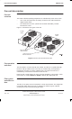
Figure 3-1 shows the two types of fan unit:
RESET BUTTONS
(ONE PER FAN)
2-FAN
UNIT
4-FAN
UNIT
SLIDE LATCH FOR
MODULE REMOVAL
Figure 3-1 View of 2-fan and 4-fan units
Fan operation
and reset
The fans draw in air from beneath the cabinet, and the air is expelled through
the door and top cabinet vents. The fans run continuously, and respond to
temperature changes to ensure adequate flow. The speed of each fan is
controlled by a heat sensor mounted on the fan hub.
Each fan has a reset button, for use if a fan has stopped or cannot start. Each
reset button is marked FRONT or REAR to identify the appropriate fan.
Filter option
and effect on
fans
The filter is an option and not essential in a clean environment. The single filter
is mounted under all the fan units. If clogged, fan airflow may be reduced,
straining fan motors and increasing fan noise.