
Service Manual


GSM-205-323
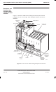
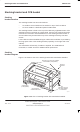
Cage backplane interface panel harness assembly (CBIA)
31st Oct 01
Technical Description: Horizon
macro
indoor
68P02902W07-B
CONTROLLED INTRODUCTION
Tech. 2–11
Interface panel
function
The interface panel provides all connection points to:
The required power sources.
External alarms (for example battery backup system alarms)
Connection points to all telecommunications links.
All connectors are linked to the backplane via the CBIA harness. Plastic
connector covers, supplied by Motorola, keep unused connectors protected
from damage by static or foreign matter and should be retained.
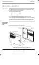
Interface panel
diagram
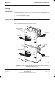
Figure 2-9 shows the locations of the interface panel connectors.
ig.239.rh
T43/BIB
AC POWER
SOCKET INPUT
DC POWER
INPUT
GPS
(if fitted)
CCB
PIX 0
EXTERNAL ALARMS
PIX 1
ICS
VENTILATION
GRID
Figure 2-9 Interface panel connector locations
Interface panel
pinouts
Interface panel pinouts are detailed in
Installation and Configuration:
(GSM-205-423)
Interface panel cabling of this service manual.