
Service Manual


GSM-205-323
Cabinet structure of Horizon
macro
indoor
31st Oct 01
Tech. 2–2
Technical Description: Horizon
macro
indoor
CONTROLLED INTRODUCTION
68P02902W07-B
Overview of
structure
description
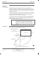
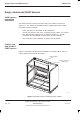
The equipped cabinet is shown in Figure 2-2. The cabinet, intended for
minimum maintenance and maximum ease of module replacement, and has
access only from the front and the top.
This chapter describes the cabinet structure and inner connections to assist
understanding of the cabinet functions. There should be no need to dismantle
the cabinet beyond Field Replaceable Unit (FRU) level.
The cabinet structure components are explained in the following sections:
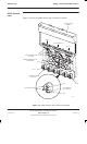
Empty cabinet and SURF harness
This section describes the empty cabinet and the SURF harness connections
between the SURF and the backplane and transceivers.
Top panel
This section describes the bare top panel with all the modules removed.
Cage backplane interface panel harness assembly (CBIA)
This section describes the CBIA. It also describes the backplane connections
between all modules, and the harness from the backplane to the interface top
panel connectors.
Door and hood
This section describes the structure and function of the door and optional hood.
Stacking bracket and CCB basket
This section describes the stacking bracket. It is used for mounting a second
cabinet on top of the first, and/or providing a mounting position for CCBs.
Space required
around cabinet
See Specifications in Chapter 1.