
Service Manual


GSM-205-323
Equipment introduction and manual definition
31st Oct 01
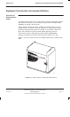
Technical Description: Horizon
macro
indoor
68P02902W07-B
CONTROLLED INTRODUCTION
Tech. 1–3
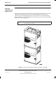
Cabinet inside
view
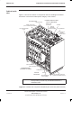
Figure 1-2 shows the location of components and main headings for detailed
information in this technical description category of the manual.
CIRCUIT
BREAKER
MODULE (CBM)
RF MODULES
POWER SUPPLIES AND
CIRCUIT BREAKER
TEMPERATURE
CONTROL SYSTEM
DIGITAL
MODULES
T43/BIB
MCUF
ALARM MODULE
FMUX/NIU/BPSM
(NOT VISIBLE)
TWO 2-FAN UNITS
ONE 4-FAN UNIT
SIX TRANSCEIVERS
(CTUs)
THREE Tx BLOCKS
(DCFs SHOWN AS EXAMPLE)
ONE SURF (Rx)
THREE PSMs
(see NOTE)
INTERFACE
PANEL
CONNECTORS
TOP SECTION OF PLINTH
(SLIDES INTO BASE PLINTH)
DC POWER IN
NOTE Three PSMs = 2 + 1 redundant (if required). An optional
hold-up battery module may be installed instead of a
redundant PSM.
Figure 1-2 Cabinet with components identified (door and base plinth removed)