
Service Manual


GSM-205-323
Equipment introduction and manual definition
31st Oct 01
Tech. 1–2
Technical Description: Horizon
macro
indoor
CONTROLLED INTRODUCTION
68P02902W07-B
Names and
acronyms for
main cabinet
equipment
This section is intended to give the reader a basic understanding of how
components interconnect.
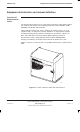
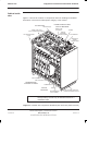
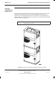
The BTS cabinet consists of the cabinet frame structure, a main cage and a top
panel, and contains the following equipment, as shown in Figure 1-2:
A digital module shelf, located in the lower right side of the cabinet. This
contains master and optional redundant digital modules:
– Fibre optic multiplexer (FMUX), 1 + 1 redundant (if required).
– Main control unit with dual FMUX (MCUF), 1 + 1 redundant (if
required).
– Network interface units (NIUs), four in total.
– An alarm board (no redundancy option).
– One or two (for redundancy) BCU power supply modules (BPSMs).
Up to three power supply modules (PSMs) and one circuit breaker module
(CBM) in the upper right portion of the cabinet. The PSMs are load
sharing, with the third PSM providing optional redundancy.
Up to six compact transceiver units (CTUs), located in the left side of the
cabinet.
Fan modules mounted in the bottom of the cabinet, two 2-fan modules
and one 4-fan module.
RF modules, mounted in the top panel, comprising transmit (Tx) blocks,
and a receive (Rx) module, the sectorized universal receiver front-end
(SURF). The various Tx blocks are listed in Specifications in this chapter.
Interface panel, mounted in the top panel, for power and customer
communications connectors.