
Service Manual


GSM-205-523
Replacing a Tx block, HCU or plate
31st Oct 01
Maintenance Information: Horizon
macro
indoor
68P02902W09-B
CONTROLLED INTRODUCTION
Maint. 2–27
Replacing a Tx
block
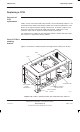
Removing a faulty Tx block
To remove a Tx block:
1. Locate the faulty Tx block, and note the RF cable connections to enable
correct reconnection to the replacement module.
WARNING
Ensure that all CTUs associated with the faulty Tx block
are identified (for example inputs to an HCU or
feedthrough plate connected to a DDF).
2. Identify the CTUs that make Tx connections to the underside of the faulty
Tx block (plus any CTUs connected to the third Tx connector on top of a
DDF). See Table 2-3.
Table 2-3 Connectors for each type of Tx block module
Tx block SMA from transceiver TX 7/16 Rx/Tx
to antenna
N-type Rx to
SURF
DCF 2 (beneath Tx block) 1 1
TDF
(including
dual band)
2 (beneath Tx block) 2 2
DDF 3 (2 beneath Tx block)
(1 on top of Tx block from HCU)
1 1
HCU 2 0 1 to next Tx block
3. Disable each CTU transmit RF power by using the shutdown_device
command at the OMC-R or from a PC connected to the MCUF. Refer to
Technical Description: BSS Command Reference (GSM–100–321)
for
information on usage and specific device codes.
4. When each CTU has been shutdown, check that the Tx status LED
(yellow) is extinguished.
5. Press and release each CTU circuit breaker button on the CBM to the out
(off) position. Ensure each RADIO STATUS LED is extinguished.
WARNING
Ensure that RF power is OFF, before disconnecting RF
cables. Severe burns may result if RF power is ON when
RF cables are disconnected.
6. Disconnect all coaxial RF cables by carefully unscrewing and pulling them
out of the Tx block sockets. Note the positions for correct replacement.
7. Using a Torx driver, unscrew and retain the two M6 torx screws holding the
Tx block to the top of the cabinet.
WARNING
Tx blocks can weigh as much as 5 kg. Handle with care.
8. Using the handles, lift the Tx block from the basket.