
Service Manual


GSM-205-523
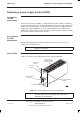
Replacing a power supply module (PSM)
31st Oct 01
Maint. 2–16
Maintenance Information: Horizon
macro
indoor
CONTROLLED INTRODUCTION
68P02902W09-B
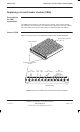
Replacing a
non-redundant
PSM
The following procedure should be followed if there are one or two PSMs fitted
in the cabinet. To replace a non-redundant PSM:
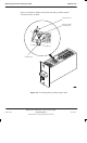
1. Set the switch of the replacement PSM to OUTPUT DISABLE.
2. Remove the blanking assembly of spare slot, if fitted, by unscrewing the
attachment screws with a torxdriver.
3. Remove the hold-up battery module, if fitted, as described in Replacing a
hold-up battery module.
4. Insert the replacement PSM in resulting or spare slot, and tighten both
module attachment screws to the correct torque (see Overview of
replacement procedures), using a torxdriver.
5. Set the replacement PSM switch to OUTPUT ENABLE. Check that the
ACTIVE LED (green) is lit.
6. Set switch of faulty PSM to OUTPUT DISABLE. The ACTIVE LED will
extinguish (the ACTIVE LED may already be off if a fault has resulted in
output failure of that PSM). The ALARM LED (red) will light, or if already lit
due to alarm state, will stay on.
7. Unscrew the faulty PSM module attachment screws using an M4
torxdriver, and remove the module. The ALARM LED will extinguish.
8. If removed in step 3, refit hold-up battery module as described in
Replacing a hold-up battery module.
9. Fit the cover plate in the vacated PSM position, if required, by tightening
the attachment screws to the correct torque with a torxdriver, as stated in
step 4.
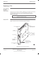
Replacing a
redundant PSM
The following procedure should be followed if there are three PSMs fitted. To
replace a redundant PSM:
1. Set the switch of replacement PSM to OUTPUT DISABLE.
2. Set switch of faulty PSM to OUTPUT DISABLE. The ACTIVE (green) LED
will extinguish (the ACTIVE LED may already be off, if a fault has resulted
in output failure of that PSM). The ALARM LED (red) will light, or if already
lit due to alarm state, will stay on.
3. Unscrew the module attachment screws by M4 torxdriver, and remove the
module. The ALARM LED will extinguish.
4. Insert the replacement PSM, and tighten both module attachment screws
to the correct torque (see Overview of replacement procedures), using
a torxdriver
5. Set switch to OUTPUT ENABLE. Check the ACTIVE LED is lit.