
Service Manual


GSM-205-523
Replacing a circuit breaker module (CBM)
31st Oct 01
Maint. 2–14
Maintenance Information: Horizon
macro
indoor
CONTROLLED INTRODUCTION
68P02902W09-B
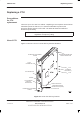
Replacing a
CBM
To replace a CBM:
1. Verify that the power source isolator is switched to OFF, and locked (if
possible).
2. Set the switch of each PSM to the OUTPUT DISABLE position.
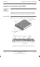
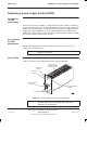
3. Unscrew both CBM module attachment screws (shown in Figure 2-6),
using a torxdriver.
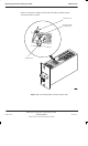
4. Pull out module, using handle-baffle.
5. Press and release all push on/push off circuit breaker buttons of the new
CBM module into the out (off) position.
6. Insert the replacement module and press firmly into place.
7. Tighten both module attachment screws to correct torque (see Overview
of replacement procedures), using an M4 Torx driver.
To restore power to the cabinet:
1. Switch on the external power supply to the cabinet.
2. Turn each PSM switch to the OUTPUT ENABLE position. Check that each
PSM has the ACTIVE (green) light on and the ALARM (red) light off.
3. Press the CBM isolator marked FANS. Check that each fan, eight in total,
is operating correctly. Any fan not started may be activated by the reset
button (marked either FRONT or REAR) on the appropriate fan unit.
4. Press the CBM circuit breaker button marked BPSM A and (if redundant
BPSM fitted) BPSM B. Check all associated digital module indicators
operate correctly.
5. Press the CBM circuit breaker button marked SURF, and if CCBs fitted the
circuit breaker buttons marked CCB0 and CCB1.
6. Press the appropriate CBM circuit breaker buttons for the CTUs fitted, and
check that the LEDs for each CTU indicate correct operation.
7. Close the door to ensure correct ventilation.
This completes the CBM replacement and power up sequence for a cabinet.