
Service Manual


GSM-205-523
Overview of replacement procedures
31st Oct 01
Maintenance Information: Horizon
macro
indoor
68P02902W09-B
CONTROLLED INTRODUCTION
Maint. 2–3
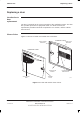
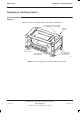
FRU locations
within cabinet
Figure 2-1 shows a cabinet with FRUs identified. Door, optional hood, stacking
bracket and CCBs are shown in the relevant FRU sections.
CIRCUIT
BREAKER
MODULE (CBM)
T43/BIB
MCUF
ALARM MODULE
FMUX/NIU/BPSM
(NOT VISIBLE)
TWO 2-FAN UNITS
ONE 4-FAN UNIT
SIX TRANSCEIVERS
(CTUs)
THREE Tx BLOCKS
(DCFs SHOWN AS EXAMPLE)
ONE SURF (Rx)
THREE PSMs
(see NOTE)
DC POWER IN
INTERFACE
PANEL
CONNECTORS
HEAT SENSORS
LOCATED ON
BACKPLANE
NOTE An optional hold-up battery module may be installed
instead of a redundant PSM.
Figure 2-1 Cabinet, without door or hood, showing FRU components