
Service Manual


GSM-205-423
Pre-power up checks
31st Oct 01
Installation & Configuration: Horizon
macro
indoor
68P02902W08-B
CONTROLLED INTRODUCTION
Inst. 4–5
Earth continuity
check
Ensure an earth continuity check has been performed on appropriate equipment
if required. Use the digital multimeter to check that the resistance of the test
equipment leads is less than 0.05 ohms.
Main equipment earths
Connect the PAT tester to the earth terminal and to the following earth points:
Antenna feeders.
AC supply input earth.
– The local electricity board termination point.
– AC distribution board.
– AC supply isolator.
NOTE
The switched isolator will not be connected to earth if it is
a double insulated device and will therefore not require
testing.
Battery box chassis.
Cabinet chassis (all cabinets).
+27 V power supply unit chassis.
Rack members.
Check that the measured resistance is less than 0.1 ohms with the tester
connected to a conductive surface (bare metal) at extreme ends of the earth
cables.
On completion of each earth check apply conductive non-oxidizing grease to the
earth connections on the earth busbar.
AC power
system
insulation
check
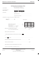
Ensure an insulation check has been performed on all ac power cables which
supply the site up to the ac input to the Cabinet. Testing must be carried out in
accordance with the BS 7671 (16th Edition <section 713-04–01 to 713-04-06>)
or IEC 364 equivalent, at the voltage levels shown in Table 4-2, using an
approved insulation tester. Check that the resistance at each point is as shown
in Table 4-2.
Table 4-2 BS7671 (16th edition) Table 71A (part of)
Parameter AC test voltage
(volts)
Minimum insulation
(megohms)
Up to and including 500 V 500 0.5
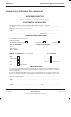
When the test has been completed, sign the completion and inspection
certificate, a sample of which may be found in Sample form 2.