
Service Manual


GSM-205-423
BTS architectures and interoperability
31st Oct 01
Installation & Configuration: Horizon
macro
indoor
68P02902W08-B
CONTROLLED INTRODUCTION
Inst. 3–11
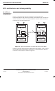
Example
configurations
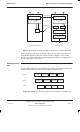
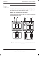
Configuration diagrams provided by the Motorola local office show top of rack
cable and antenna connections for mixed product configurations, together with
details of external RF loads required. Figure 3-9, Figure 3-10 and Figure 3-11
are examples of the type of diagram that can be provided.
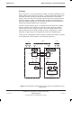
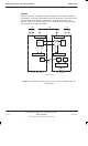
GSM900 2/2/2 configuration using two cabinets
In this configuration, there are no split cells, and therefore no uplink/downlink
connections between the cabinets. The CBFs are 2-input devices, consequently
no external RF loads are required.
Sector 2
2B 1B 0B 2A 1A 0A B A
BLANK BLANKDCF
CBF BLANK CBF
EXT
Sector 3 Sector 1
Horizon
macro
M-Cell
6
Figure 3-9 GSM900 mixed Horizon
macro
/ M-Cell
6
2/2/2 configuration using
two cabinets