
Service Manual


GSM-205-423
BTS architectures and interoperability
31st Oct 01
Installation & Configuration: Horizon
macro
indoor
68P02902W08-B
CONTROLLED INTRODUCTION
Inst. 3–7
Transmit path
M-Cell
6
combining
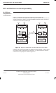
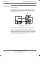
When configuring the downlink paths for a cell using three carriers or more, it
may be necessary to provide additional external RF load(s) for the combiners.
This is illustrated by Figure 3-6, which shows a typical M-Cell
6
combining
arrangement for a 4-carrier cell.
Hybrid
HybridHybrid
Duplexer
Load
Load
3IP CBF
HCOMB
External
load
One carrier from each of four transceivers
Carrier 1 Carrier 2 Carrier 3 Carrier 4
Figure 3-6 Typical M-Cell
6
arrangement for combining four carriers
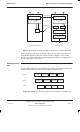
Carriers 1 and 2 are combined in a hybrid combiner (HCOMB) module. The
output from this module provides one of the three inputs to the 3IP CBF. The
HCOMB is equipped with an internal RF load, and is therefore self–contained.
The 3IP CBF requires one RF load for each of the two hybrids it contains, but is
equipped with only a single internal RF load. An additional load is therefore
provided for this purpose on the HCOMB casing.