
Service Manual


GSM-205-423
BTS architectures and interoperability
31st Oct 01
Installation & Configuration: Horizon
macro
indoor
68P02902W08-B
CONTROLLED INTRODUCTION
Inst. 3–5
DCS1800
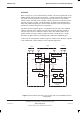
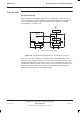
Refer to Figure 3-4. In the Horizon
macro
cabinet, low noise amplification in the
SURF module first boosts the Rx signal by +13 dB. Separate Rx outputs from
the SURF are then discretely routed to relevant transceivers in the master
cabinet, and to the LNA in the extender cabinet. Since the LNA boosts the Rx
signal by a further +13 dB, a 13 dB attenuator is placed in the signal path to
offset this additional signal gain, which would otherwise result in signal levels
outside the permitted range for the transceivers.
The Rx
div
signal is similarly given a +13 dB boost by the LNA in the extender
cabinet. Separate Rx
div
outputs from the LNA are then discretely routed to
relevant receivers in the extender cabinet, and to the SURF module in the
master cabinet. Since the SURF provides a further +13 dB boost, a 13 dB
attenuator is again placed in the signal path to offset this additional gain.
In this way, the arrangement shown in Figure 3-4 delivers Rx and Rx
div
signals
to the uplink path in both cabinets, at the required signal level.
To NIU and Abis
Interface
Rx
Rx
div
M-Cell
6
(Master)
CTU
Cell A
Cell B Cell C
Rx
div
Rx Rx Rxdiv
Duplexer
SURF
+13 dB
–13 dB
+13 dB
Rx
div
Rx
LNA
Rx Rx
div
–13 dB
TCU
Horizon
macro
(Extender)
Rx
div
Rx
FMUX
MCU
FMUX
Fibre
optic
link
Duplexer
FOX
Figure 3-4 Functional overview of the receive path for a DCS1800 split cell
configuration