
Service Manual


GSM-205-423
BTS architectures and interoperability
31st Oct 01
Inst. 3–2
Installation & Configuration: Horizon
macro
indoor
CONTROLLED INTRODUCTION
68P02902W08-B
BTS architectures and interoperability
M-Cell
6
and
Horizon
macro
architectures
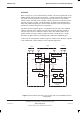
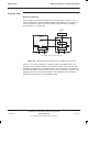
Figure 3-1 represents the high level architecture of the M-Cell
6
and
Horizon
macro
BTSs. Both systems provide an optical interface for connection to
remote transceivers, which in a normal installation would be used to connect to
transceivers of the same product type.
CTU
RF coupling
MCUF FMUX
Network termination
functions
FMUX
Horizon
macro
M-Cell
6
Fibre optic links
to remote radios
TCU
RF coupling
MCU
FMUX
Network termination
functions
FOX
Figure 3-1 High level architecture of M-Cell
6
and Horizon
macro
BTSs
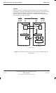
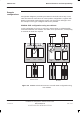
However, since the optical interface is identical for both products, it can be used
to link an M-Cell
6
to Horizon
macro
transceivers, or a Horizon
macro
to M-Cell
6
transceivers. The principle is shown in Figure 3-2.