
Service Manual


GSM-205-423
Installing a hold-up battery module
31st Oct 01
Installation & Configuration: Horizon
macro
indoor
68P02902W08-B
CONTROLLED INTRODUCTION
Inst. 2–61
Installing a hold-up battery module
Introduction to
hold-up module
installation
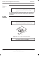
The hold-up battery module is an optional item fitted in the PSM shelf within the
CBIA main cage, in any empty slot or in place of the redundant PSM. It may be
installed at the same time as the Horizon
macro
BTS or retrospectively. There is
no requirement to take the BTS out of service to retrofit the hold-up battery
module.
Installing a
hold-up battery
module
WARNING The batteries are capable of supplying high short circuit
currents and as such present a high energy hazard.
To install a hold-up battery module:
1. Check that the hold-up battery module enable switch is set to O (off).
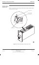
2. Cut the cable tie that secures the jumper lead to the isolation connection
access hatch. Open the access hatch by turning the fastener a quarter
turn anticlockwise and lifting.
3. Fit the jumper lead between the battery spade terminals as shown in
Figure 2-40. Close the access hatch and turn the fastener a quarter turn
clockwise to secure.
4. Set switch of the redundant PSM, (if fitted) to OUTPUT DISABLE. The
ACTIVE LED (green) will extinguish. The ALARM LED (red) will light, or if
already lit due to alarm state, will stay on.
5. Remove redundant PSM or blanking assembly from the spare slot, by
unscrewing attachment screws with a torxdriver.
WARNING
The hold-up battery module weighs 5.9 kg. Handle with
care.
6. Insert hold-up battery module in spare slot.
7. Ensure hold-up battery module is firmly in position and tighten both
module attachment screws using a torxdriver. Tighten to a torque of
2.2 Nm.
8. Set the hold-up battery module enable switch to I (on). Check that the
CHARGE LED (green) is lit.
NOTE
The ACTIVE LED (green) will not light until 1.5 to 2 hours
after installation. The ALARM LED (red) may also be lit if
the initial battery voltage is below 19 V dc (+/–0.25 V).