
Service Manual


GSM-205-423
Installing and connecting power and earth cabling
31st Oct 01
Installation & Configuration: Horizon
macro
indoor
68P02902W08-B
CONTROLLED INTRODUCTION
Inst. 2–55
Cabinet and
ESP earthing
points
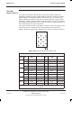
The main earth connection point is on the top interface panel, with a 10 mm M6
threaded stud, adjacent to the dc input. This connection is for protective
earthing and functional earthing of the cabinet.
Additional internal earths are:
Door to cabinet frame.
Main cage to interface panel above PSM.
Tx block top panel to interface panel, near dc input.
AC input connector to interface panel at rear of panel.
Enclosure to interface panel, at rear near dc input.
An earthing wrist strap must be worn when handling electronic modules,
including the MCUF, FMUX, NIU, alarm module, CTU, and SURF. An ESP
earthing connection point is provided above the leftmost PSM.
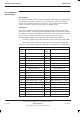
Power supply
cable colour
coding
CAUTION Ensure correct PSMs are fitted to match the supply source
voltage.
+27 V dc cabinets
To connect a +27 V dc (negative earth) cabinet to the main dc power source.
Observe the following rules:
The 27 volt (+ve) power cable is red.
The 0 volt (–ve) cable is black.
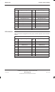
–48/60 V dc cabinets
To connect a –48/60 V dc (positive earth) cabinet to the main dc power source,
Motorola recommends using a 35 sq. mm dc input power cable with a maximum
length of 24 m. Observe the following rules:
The –48/60 volt (–ve) power cable is blue.
The 0 volt (+ve) cable is black.