
Service Manual


GSM-205-423
Interface panel cabling
31st Oct 01
Inst. 2–52
Installation & Configuration: Horizon
macro
indoor
CONTROLLED INTRODUCTION
68P02902W08-B
PIX conditions
input/output
PIX outputs
PIX outputs comprise 4 relay contacts controlled by the alarm board and MCUF.
The relays have multiple contacts, some normally open and some normally
closed. The contacts are rated for 1A at 30 V. The contacts may be used for
control of external equipment such as fans or audible alarms.
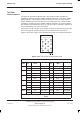
PIX inputs
PIX inputs comprise 16 connections to external sensors. These inputs report
alarms to the BSC, via the alarm board and MCUF, which forwards the alarms to
the OMC-R. The end-user supplies the external sensors. Each sensor connects
across an opto-coupled pair of PIX inputs (eight per PIX connector).
All sensors must be dry-contact type with the following specification:
5 kohms or greater across sense inputs for logic 1 (PIX opto-coupler off).
500 ohms or less across sense inputs for logic 0 (PIX opto-coupler on).
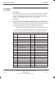
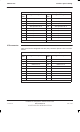
Table 2-11 shows PIX0 connections and Table 2-12 shows PIX1 connections.
Table 2-11 PIX0 pin connections (37-way D-type)
Pin
No
Signal/Description Pin
No
Signal/Description
1 Site input Ext 1–1 19 Not connected
2 Site input Ext 2–1 20 Site input Ext 1–2
3 Site input Ext 3–1 21 Site input Ext 2–2
4 Site input Ext 4–1 22 Site input Ext 3–2
5 Site input Ext 5–1 23 Site input Ext 4–2
6 Site input Ext 6–1 24 Site input Ext 5–2
7 Site input Ext 7–1 25 Site input Ext 6–2
8 Site input Ext 8–1 26 Site input Ext 7–2
9 Not connected 27 Site input Ext 8–2
10 Not connected 28 spare
11 Site output relay 1 – NO 29 Site output relay 1 – NC
12 Site output relay 2 – NO 30 Site output relay 1 – COM
13 Site output relay 2 – NC 31 Site output relay 2 – COM
14 Site output relay 3 – NO 32 Site output relay 3 – NC
15 Site output relay 4 – NO 33 Site output relay 3 – COM
16 Site output relay 4 – NC 34 Site output relay 4 – COM
17 Not connected 35 Not connected
18 Not connected 36/37 Not connected