
Service Manual


GSM-205-423
Interface panel cabling
31st Oct 01
Installation & Configuration: Horizon
macro
indoor
68P02902W08-B
CONTROLLED INTRODUCTION
Inst. 2–51
T43 (CIM)
interconnection
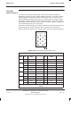
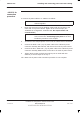
The Type 43 Interconnect Board (T43), also known as CIM, provides the
impedance matching and line isolation between the E1/T1 circuit lines and the
CBIA backplane. The board provides an interface for up to six input and six
output unbalanced coaxial 75 ohm lines. 12 transformers are used to provide
impedance matching and line isolation between the E1/T1 circuit lines and the
NIU module. Each transformer has a 1:1.25 turns ratio to match the external 75
ohm and backplane 120 ohm connections.
Connection is made using a 37-pin D-type connector to the interconnect board
and twelve type 43 coaxial connectors to the external E1/T1 circuit lines.
Figure 2-38 shows a typical T43, and Table 2-10 lists the T43 interconnections.
J1
J2
J5
J4
J7
J8
J10
J13 J11
J14
J16
J17
J0
Figure 2-38 Type 43 interconnect board (T43)
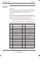
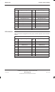
Table 2-10 T43 interconnections
NIU/
port
Pin
no
Equipment
/ Ext
Pin no Pin
no
Equipment
/ Ext
Pin no
A0/0 J0-1 Tx1+ J1 centre J0-20 Tx1– J1 shield
J0-2 Rx1+ J2 centre J0-21 Rx1– J2 shield
B0/0 J0-4 Tx4+ J4 centre J0-23 Tx4– J4 shield
j0-5 Rx4+ J5 centre J0-24 Rx4– J5 shield
A0/1 J0-7 Tx2+ J7 centre J0-26 Tx2– J7 shield
J0-8 Rx2+ J8 centre J0-27 Rx2– J8 shield
B0/1 j0-10 Tx5+ J10 centre J0-29 Tx5– J10 shield
j0-11 Rx5+ J11 centre J0-30 Rx5– J11 shield
A1/0 J0-13 Tx3+ J13 centre J0-32 Tx3– J13 shield
J0-14 Rx3+ J14 centre J0-33 Rx3– J14 shield
B1/0 J0-16 Tx6+ J16 centre J0-35 Tx6– J16 shield
J0-17 Rx6+ J17 centre J0-36 Rx6– J17 shield
Connector J0 pins 3,6,9,12,15,18,19, 22, 25, 28, 31, 34 and 37 are not
used