
Service Manual


GSM-205-423
Interface panel cabling
31st Oct 01
Installation & Configuration: Horizon
macro
indoor
68P02902W08-B
CONTROLLED INTRODUCTION
Inst. 2–49
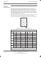
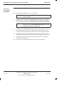
GPS connector
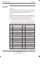
Table 2-7 lists the GPS connector pinouts.
NOTE
The GPS connector is optional on later BTS cabinets.
Table 2-7 GPS pin connections (15-way D-type)
Pin
No
Signal/Description Pin
No
Signal/Description
1 GPS power 1 9 GPS power 2
2 Not connected 10 Not connected
3 chassis earth 11 PPS positive
4 Tx negative 12 PPS negative
5 Tx positive 13 Rx positive
6 Rx negative 14 VPP
7 Earth 15 GPS return 2
8 GPS return 1
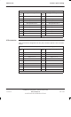
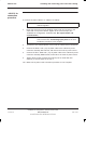
CCB connector
Table 2-8 lists the CCB connector pinouts. This provides a single connector, to
provide power for up to two CCBs.
NOTE
The CCB connector is not currently used on GSM850 or
PCS1900 BTS variants.
Table 2-8 CCB pin connections (15-way D-type)
Pin
No
Signal/Description Pin
No
Signal/Description
1 Not connected 9 Not connected
2 Not connected 10 Not connected
3 CCB0 27 V 11 Earth
4 CCB0 27 V 12 Earth
5 Not connected 13 Not connected
6 CCB1 27 V 14 Earth
7 CCB1 27 V 15 Earth
8 Not connected