
Service Manual


GSM-205-423
Interface panel cabling
31st Oct 01
Inst. 2–48
Installation & Configuration: Horizon
macro
indoor
CONTROLLED INTRODUCTION
68P02902W08-B
Connector
pinout tables
CAUTION Keep the plastic connector covers, supplied by Motorola,
on unused connectors to protect from damage by static or
foreign matter.
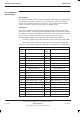
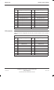
The following tables list the connector pinouts:
External alarms see Table 2-6 and accompanying information.
GPS see Table 2-7.
CCB see Table 2-8.
BIB see Table 2-9.
T43 see Table 2-10.
PIX0 see Table 2-11.
PIX1 see Table 2-12.
ICS see Table 2-13.
NOTE
Some pin connections only refer to indoor or outdoor
cabinets.
External alarm
connector
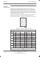
The external alarms connector is used by the battery backup system (BBS).
When this connector is not in use, a shorting plug, Motorola part number
2886169N01, is inserted. This plug must be removed to allow connection of the
alarm cable from the BSS and should be retained for refit during
decommissioning of BBS. The external alarm connector carries different alarms
in the Horizon
macro
outdoor.
The shorting plug joins pairs of pins as shown in Table 2-6.
Table 2-6 External alarms indoor pin shorts (37-way D-type)
Pin Nos Pin Nos Pin Nos Pin Nos
1 + 2 11 21+22 32
3 +4 12 23+24 33
5+6 13+14 25+26 34
7+8 15+16 27+28 35
9 17+18 29+30 36+37
10 19 +20 31