
Service Manual


GSM-205-423
Suggested RF configurations
31st Oct 01
Installation & Configuration: Horizon
macro
indoor
68P02902W08-B
CONTROLLED INTRODUCTION
Inst. 2–25
Suggested RF configurations
Overview of
configuration
diagrams
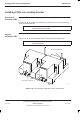
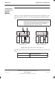
The following series of RF configuration diagrams show suggested ways of
connecting together Horizon
macro
SURF and Tx blocks to meet different
operational requirements. The series of diagrams is by no means exhaustive,
and numerous alternative configurations may be adopted to achieve the same
aim.
Each Horizon
macro
cabinet is represented by a SURF module and three Tx
blocks. Interconnecting cables are identified by a label; N01, 2, 3 or 4. Further
details of each cable type are shown in Table 2-3. Antenna connecting cables,
not supplied as part of the Horizon
macro
equipment, are shown as dotted lines.
With the exception of Figure 2-33 and Figure 2-34, the diagrams are applicable
to GSM850, EGSM900, DCS1800 or PCS1900 single band operation, although
only the 1800 SURF module is illustrated.
NOTE
Dual band 900 and 1800 SURFs are available, but 850
and 1900 SURFs are only available as single band.
Figure 2-33 shows one way of achieving dual band operation using two
Horizon
macro
cabinets. A single band 1800 SURF is installed in one cabinet
and a dual band 900 SURF in the other. Figure 2-34 shows another, using one
of each type of dual band SURF.
Diversity is assumed in the majority of RF configuration diagrams shown here,
Figure 2-15 being the exception. Other non diversity configurations can be
derived from this figure by ensuring that the single receive path is always
connected to branch A at the SURF module.
Digital connections
Digital connections between cabinets are not shown in the following diagrams.
Fibre optic cables used to provide digital connections between cabinets are
described in Connecting fibre optic cables.
Depopulated site configurations
The purpose of a depopulated site configuration is to allow customers to provide
a future expansion capability, at the time of installation. The diagram showing
the final target configuration is to be used to connect Tx blocks, SURF and
antennas. Depopulated site configurations are supplied with fully equipped RF
section to achieve the target configuration, with CTUs only fitted to alternate
slots. CTUs are fitted in slots 0, 2 and 4. Unused Tx block SMA connectors must
be fitted with 50 ohm terminating loads.