
Service Manual


GSM-205-423
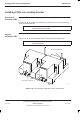
Installing CCBs into stacking bracket
31st Oct 01
Installation & Configuration: Horizon
macro
indoor
68P02902W08-B
CONTROLLED INTRODUCTION
Inst. 2–19
Installing CCBs
Follow these procedures to install CCBs.
Cabinet preparation
1. Ensure the SMA to N-type feedthrough plates are fitted inside the Tx block
basket, with SMA cables installed from CTUs underneath. Ensure the
N-type cables are connected to the feedthrough plates and draped over
the front of the cabinet.
2. Ensure the stacking bracket is fitted to lower cabinet. If not, refer to Fitting
a stacking bracket.
Fitting CCBs into basket
1. Place the CCB basket onto a flat surface.
2. Place the CCBs into the basket and secure with four M6 screws on the
front and two M8 screws at the back. Tighten to the correct torque (see
Installation & Configuration: GSM-205-423
Site requirements and
considerations).
3. Insert each CCB control board, then secure the control board cover with
four M4 screws. Tighten to the correct torque (see
Installation &
Configuration: GSM-205-423
Site requirements and considerations).
4. Connect the phasing lead between the CCB control boards.
Fitting basket to stacking bracket
NOTE Due to space limitations and the need for flexibility,
Motorola recommends the use of Superflex jumper cables
for antenna connections to the CCBs.
1. Slide the basket part way into the stacking bracket, and connect antennas
to the CCBs.
2. Slide the CCB basket fully home.
3. Connect the six N-type to N-type RF cables from the feedthrough plates to
the CCB inputs.
4. Attach the CCB basket bar to the sides of the stacking bracket with the
two captive screws. The bar is then directly underneath the basket captive
screws.
5. Attach the CCB basket bar to the basket with the three captive screws on
the basket.
6. Connect the power cable to each CCB from the single connector (marked
CCB) on the interface panel, shown in Figure 2-36.
7. Fit the front cover onto the stacking bracket, pushing it in so that it drops
into position on the side lugs, as described in Fitting the stacking
bracket front cover.
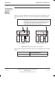
The fully installed CCBs are illustrated in Figure 2-10 and Figure 2-12.