
Service Manual


GSM-205-423
Installation overview
31st Oct 01
Installation & Configuration: Horizon
macro
indoor
68P02902W08-B
CONTROLLED INTRODUCTION
Inst. 2–3
Cabinet view
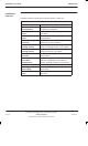
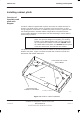
Figure 2-1 shows the main components of a fully equipped cabinet.
CIRCUIT
BREAKER
MODULE (CBM)
RF MODULES
POWER SUPPLIES AND
CIRCUIT BREAKER
TEMPERATURE
CONTROL SYSTEM
DIGITAL
MODULES
T43/BIB
MCUF
ALARM MODULE
FMUX/NIU/BPSM
(NOT VISIBLE)
TWO 2-FAN UNITS
ONE 4-FAN UNIT
SIX TRANSCEIVERS
(CTUs)
THREE Tx BLOCKS
(DCFs SHOWN AS EXAMPLE)
ONE SURF (Rx)
THREE PSMs
(see NOTE)
DC POWER IN
INTERFACE
PANEL
CONNECTORS
TOP SECTION OF PLINTH
(SLIDES INTO BASE PLINTH)
NOTE Three PSMs = 2 + 1 redundant (if required). An optional
hold-up battery module may be installed instead of a
redundant PSM.
Figure 2-1 Cabinet with components identified (door and hood removed)
E1/T1 line
testing
If an E1/T1 line has been provided, contact the local MSC and, at the earliest
opportunity, arrange to test the line back to the MSC.