
Service Manual


GSM-205-323
FMUX module
31st Oct 01
Technical Description: Horizon
macro
indoor
68P02902W07-B
CONTROLLED INTRODUCTION
Tech. 6–23
FMUX
functional
diagram
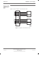
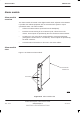
Figure 6-9 shows a block diagram of the FMUX module.
FIBRE OPTIC
RECEIVER
FIBRE OPTIC
TRANSMITTER
BACKPLANE CONNECTOR
Rx
DATA
Tx
DATA
SELECT
CONTROL
(FROM
MCUF)
6
MUX/
DEMUX
2:1
SELECT
TO MCUF (IF
MASTER
CABINET)
MANCHESTER
ENCODED
Tx/Rx
6
TO FMUX IN
ANOTHER
CABINET
TO FMUX IN
ANOTHER
CABINET
TO CTUs OR
TCUs (IF
EXTENSION
CABINET)
Figure 6-9 Functional diagram of FMUX module
FMUX
functional
explanation
The MCUF transmits and receives a 2.048 Mbit/s data stream link to each
operational transceiver. In the master cabinet this is achieved by the backplane,
without using an FMUX.
If the transceiver is in an extension cabinet, the master cabinet FMUX combines
the data stream with up to five others (see Figure 6-9), and then converts the
electronic signal to fibre optic, for onward transmission to the extension cabinet.
At the extension cabinet, another FMUX converts the fibre optic signal back to
electronic form, for transmission to the transceivers.
The data stream return from the extension cabinet is a reverse of the above.
The multiplexer/demultiplexer can support up to six transceiver links. It uses a
16.384 Mbit/s Manchester encoded serial data link organized as 256 x eight bit
timeslots in a 125s frame. Manchester coding is used to detect errors,
indicated at timeslot zero for each transceiver, enabling error correction at the
other FMUX.