
Service Manual


GSM-205-323
MCUF
31st Oct 01
Technical Description: Horizon
macro
indoor
68P02902W07-B
CONTROLLED INTRODUCTION
Tech. 6–11
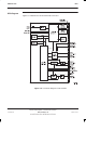
ASIC/network and processor link switching
The ASIC supports a maximum of six network links and two main processor
links. The data to/from these links can be switched to/from any timeslot on other
links connected to the ASIC.
The two links to the main processor allow it to route HDLC and other links to the
appropriate place:
24 HDLC timeslots for the BCF RSS channel to each transceiver.
Four timeslots for NIU control channels (two local, two redundant).
Sync processor code load channel.
Two channels for RSL links.
One HDLC channel occupying up to three timeslots to the redundant
MCUF.
Sync block
functionality
The sync block is controlled via the parallel interface of the main processors.
The sync block is responsible for site synchronization functions. It generates all
required local references from a high stability local clock source. This clock
source may also be locked to the incoming network clocks.
The sync clock source is in the form of a crystal oscillator (OCXO) which warms
up for phase locking in 4 minutes, and achieves frequency stabilization in 15
minutes.
Site frame reference generation and re-timing includes:
2.048 MHz - For serial communications.
16.384 MHz - For FMUX communications.
125 s - For NIU framing and transceiver framing.
60 ms- For transceiver GSM timing.
6.12 s - For GSM superframe.
The reference clocks available to the sync block are:
Six network extracted clocks (E1/T1 source via NIUs). Any of the NIU
modules under control of the MCUF can extract a reference clock from an
E1/T1 link and pass to the Sync block.
CAL port. The CAL port can be used to calibrate the sync block clock via
MMI commands. The reference output provides a monitoring point.
Redundant MCUF link.