
Service Manual


GSM-205-323
MCUF
31st Oct 01
Tech. 6–8
Technical Description: Horizon
macro
indoor
CONTROLLED INTRODUCTION
68P02902W07-B
PCMCIA interface
The PCMCIA card is located on the front panel of the MCUF, and is used for:
Code Storage Facility Processor (CSFP) memory.
Rapid site initialization.
The PCMCIA socket is an industrial standard 68 pin single socket, fitted with an
ejector. The PCMCIA interface supports rev 2.1 type I and II cards.
The 20 Mbyte card can be write enabled, for upgrade of site information, or
disabled to protect card use for other sites or secure the site code.
Front panel
switches and
indicators
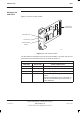
The front panel of the MCUF module has two reset switches as shown in
Figure 6-3:
FULL is a hard reset (power up - removes software from the memory).
CPU is a soft reset (this resets the MCUF main processors, but the
software remains in RAM).
A hard reset results in the software being reloaded to the DRAM in the same
way as normal power up.
NOTE
During the CPU (soft) reset, pressing CPU reset again will
perform a hard reset. Pressing the CPU reset button twice
thus has the same effect as a hard reset.
The MCUF has two front panel LEDs (one green and one red) as shown in
Figure 6-3, with indications as shown in Table 6-2.
CAUTION
When red and green LEDs are flashing, the boot code is
downloading into non-volatile memory for software
upgrade. Do not remove power or reset the cabinet until
downloading has been completed, as this will corrupt the
non-volatile memory. If boot code is corrupted, contact the
Motorola Customer Network Resolution Centre, requesting
the boot code restoration procedure and the appropriate
boot code file.
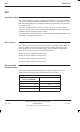
Table 6-2 MCUF front panel LED indication
Red Green Status
Off Off Board not powered up or in rest cycle
Off On Normal operation
On Off Fault condition
Flashing Flashing Non-volatile memory boot code upgrade
(Do not remove power nor reset – see CAUTION)