
Service Manual


GSM-205-323
MCUF
31st Oct 01
Technical Description: Horizon
macro
indoor
68P02902W07-B
CONTROLLED INTRODUCTION
Tech. 6–7
Link to
redundant
MCUF
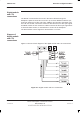
The link to the redundant MCUF is similar to a transceiver link, but does not
have the BBH capability, or the link delay measurement and compensation
facility. The 6.12 s, and 60 ms signals, are inserted into timeslots 8 and 16.
When the MCUF is in slave mode, timeslot and E1/T1 clock information is
extracted from the MCUF link and passed to the sync block.
The main processor HDLC link to the redundant MCUF can be routed in any
unused timeslot(s) of this link.
The ASIC can switch any timeslot on the redundancy link to any timeslot on any
of the other links connected to it such as the transceiver links, network links,
redundancy link or processor links.
Front panel
interfaces
TTY interface
A standard TTY interface is provided on the front panel, of 9.6 kbit/s (8 bits, no
parity, 1 stop bit (8 N 1)). A local maintenance terminal can be attached to this
port to use the MMI (Man Machine Interface) of the MCUF.
Debug and BDM ports
Two front panel ports are for Motorola factory and development use only:
The debug port, consists of a TTY connection to the sync processor to
access sync firmware, together with other connections to the ASIC and
main processors.
The Background Debug Mode (BDM) port is used for low level debugging
of the main processors.
FMUX fibre optic connections
There are fibre optic connections from the MCUF internal FMUX modules. The
fibre optic connectors enable connection to FMUX modules in other cabinets for
additional transceivers.
CAL port
The CAL port on the front panel of the MCUF can be used to calibrate the sync
block clock via MMI commands. The 8 kHz reference output is used in GCLK
calibration procedure (see
Installation & Configuration BSS Optimization
(GSM-100-423)
).