
Service Manual


GSM-205-323
Overview of digital modules
31st Oct 01
Technical Description: Horizon
macro
indoor
68P02902W07-B
CONTROLLED INTRODUCTION
Tech. 6–1
Overview of digital modules
Overview and
redundancy
Digital modules provide the Horizon
macro
indoor equivalent of M-Cell
6
micro
base control unit (µBCU) functionality. They are located in the bottom right side
of the CIBA maincage, and are electronically interconnected through the
backplane. Fibre optic connections are at the front of the appropriate modules.
Each digital module is assigned A (master) or B (redundant), with one BPSM
(µBCU Power Supply Module) for A and one BPSM for B. The alarm module is
not assigned to A or B, as it is supplied by both BPSMs for redundancy.
The master MCUF is assigned to A, and the redundant MCUF to B, each with
an associated FMUX.
The four NIUs are used by the operational MCUF, but two NIUs are powered by
BPSM A and two NIUs by BPSM B.
All slots are annotated with the legend of the appropriate module and located as
shown in Figure 6-1.
Digital module
and BPSM
locations
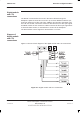
Figure 6-1 shows the position of modules within the digital module shelf.
ig.322.rh
ALARM
MODULE
NIU B0
NIU B1
BPSM
BPSM
FMUX
FMUX
MCUF A
MCUF B
NIU A0
NIU A1
REDUNDANT (B)
MASTER (A)
DIGITAL
MODULE SHELF
Figure 6-1 Digital and BPSM module locations, including optional redundancy