
Service Manual


GSM-205-323
CCB
31st Oct 01
Technical Description: Horizon
macro
indoor
68P02902W07-B
CONTROLLED INTRODUCTION
Tech. 5–49
CCB functional
description and
diagram
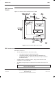
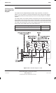
The CCB has three independently tuneable cavity resonators, as shown in
Figure 5-34. The cavities are narrow band devices which pass transmit signals
at the cavity tuned (resonant) frequency. The three cavity outputs are coupled
together.
The CCB cavities are tuned by software commands from the CCB control board.
Control data is sent from the CTU, via the coaxial cable, to the CCB. This data is
separated from the RF signal at the bias tee, and sent to the CCB control board.
The CCB control board then sends control signals through the control bus to the
motor control of the CCB cavity of the same transceiver.
CCB tuning change
Time taken
One cavity retuned and verified 8 seconds
Three cavities retuned and verified 19 seconds
Figure 5-34 Functional diagram of CCB