
Service Manual


GSM-205-323
CCB
31st Oct 01
Tech. 5–46
Technical Description: Horizon
macro
indoor
CONTROLLED INTRODUCTION
68P02902W07-B
CCB
CCB overview
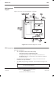
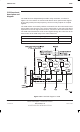
The Cavity Combining Block (CCB) has EGSM900 and DCS1800 variants. A
CCB consists of three independently tuneable cavity resonators, one per CTU.
NOTE
CCBs are not currently available for the GSM850 or
PCS1900 BTS variants.
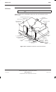
The CCBs are fitted in the CCB basket in the stacking bracket. The basket can
contain up to two CCBs, one for three CTUs. The two CCBs cannot be in
different cabinets because of the short phasing lead connecting the two.
Configurations where five or more carriers per sector are required could utilize
CCBs.
The recommended minimum channel spacing between cavities is 800 kHz.
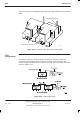
There are two types of CCB:
Master CCB with Band Pass Filter (BPF) and control board.
Extension CCB, identical to the master CCB but without the BPF and only
having a control board if redundancy is required.
Unlike the Tx blocks, the CCB has no duplexing capability. If a single Rx/Tx
antenna is used then connection to the CCB must be via an external high power
duplexer.
CCB control
board (TCB)
and set switch
The CCB control board is also known as the Transmit Antenna Transceiver
Interface (TATI) control board (TCB).
The CCB control board controls the interface to the CTU. This allows different
vendor CCBs to be installed without requiring amended CTU software.
The address of the control board is set manually using an 8 bit DIL switch, set
by Motorola. Data links are automatically set up.
TCB and link
redundancy
The redundant TCB has the ability to maintain the separated CCB, if the
inter-CCB link fails.