
Service Manual


GSM-205-323
Dual band TDF
31st Oct 01
Technical Description: Horizon
macro
indoor
68P02902W07-B
CONTROLLED INTRODUCTION
Tech. 5–41
Dual band TDF
functional
diagram
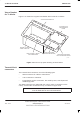
Figure 5-26 shows a functional diagram of the dual band TDF.
Figure 5-26 Dual band TDF functional diagram
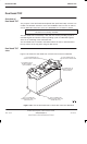
Dual band TDF
connectors
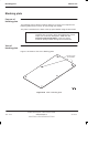
Each dual band TDF connects to:
The Tx output of one 900 CTU and one 1800 CTU, using SMA
connectors. The two connectors are underneath the dual band TDF.
One 900 MHz antenna and one 1800 MHz antenna. Each antenna is used
for both Rx and Tx, and each is connected to the dual band TDF using
7/16 connectors. These connectors are on top of the dual band TDF.
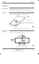
A SURF module with dual band capability. Two N-type connectors, located
on top of the dual band TDF, connect one receive path to the SURF’s
900 MHz input and one receive path to the SURF’s 1800 MHz input.