
Service Manual


GSM-205-323
TDF
31st Oct 01
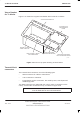
Technical Description: Horizon
macro
indoor
68P02902W07-B
CONTROLLED INTRODUCTION
Tech. 5–39
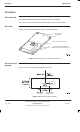
TDF functional
diagram
Figure 5-24 shows a functional diagram of the TDF.
Figure 5-24 TDF functional diagram
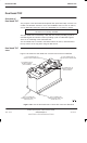
TDF connectors
Each TDF connects to:
The Tx outputs of two CTUs, using SMA connectors. The two connectors
are underneath the TDF.
Two antennas, each for both Rx and Tx, using 7/16 connectors. These
connectors are on top of the TDF.
The SURF, using two N-type connectors. These connectors are on top of
the TDF.