
Service Manual


GSM-205-323
CTU
31st Oct 01
Tech. 5–14
Technical Description: Horizon
macro
indoor
CONTROLLED INTRODUCTION
68P02902W07-B
CTU Tx function
IQ modulator
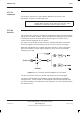
Figure 5-6 shows a functional diagram of the IQ modulator. IQ modulator data
for eight timeslot channels is applied to the modulator state machine. This data
is encoded, serial-to-parallel converted and split into quadrature components.
The quadrature components are D/A converted and applied to a quadrature
modulator to create a Gaussian minimum shift keyed (GMSK) carrier at an
intermediate frequency (IF).
Figure 5-6 IQ modulator functional diagram
IF and exciter stages
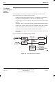
Figure 5-7 shows a functional diagram of the IF and exciter stages. The low
level modulated carrier is applied to a combination of analogue and digital
attenuators for RF power control. The power control data comes from the digital
sections of the XCVR. The output of the power control elements is further
amplified by an exciter chain to drive the power amplifier.
The GMSK modulated IF is filtered and applied to the input of a controlled gain
amplifier for transmitter pulse sloping (ramped). The ramped signal is filtered
and then mixed with the main transmitter injection and is upconverted to the
final transmit channel frequency.
Figure 5-7 IF and exciter functional diagram