
Service Manual


GSM-205-323
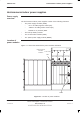
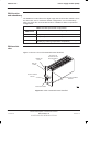
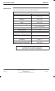
Hold-up battery module
31st Oct 01
Technical Description: Horizon
macro
indoor
68P02902W07-B
CONTROLLED INTRODUCTION
Tech. 4–7
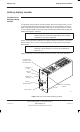
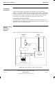
Front panel
switch and
LEDs
Front panel enable switch
The rocker style switch mounted on the front panel is used to enable the output
of the hold-up module.
Front panel LED indicators
The front panel LEDs function as follows:
ACTIVE (green).
Normally lit, this LED indicates that the module is capable of powering
cabinets. The ACTIVE LED flashes during discharge.
ALARM (red).
Normally unlit, when lit continuously this LED indicates one or more of the
following alarm conditions exists:
– Battery charger fail.
– Input voltage drops below 88 V ac (110 V systems)
or below 150 V ac (230 V systems).
– Enable fail, the module is not receiving an enable signal from the
Horizon
macro
backplane.
When the ALARM LED is flashing the batteries have failed and are not
capable of providing sufficient energy to supply a ten second hold-up.
NOTE
If a battery failure occurs, the batteries may have reached
the end of life. The hold-up battery module is disabled and
must be returned to Motorola for repair.
CHARGE (green).
The CHARGE LED is lit while batteries are charging.
Hold-up module
batteries
The hold-up module contains two 12 V batteries connected in series to provide
a nominal output of 24 V dc, with a capacity of 5 Ah.
Input protection is provided by a 3.15 A fuse mounted on the battery charger
PCB, this fuse is not user replaceable. The hold-up module must be returned to
Motorola for repair.