
Service Manual


GSM-205-323
Power supply module (PSM)
31st Oct 01
Technical Description: Horizon
macro
indoor
68P02902W07-B
CONTROLLED INTRODUCTION
Tech. 4–3
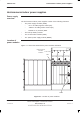
PSM location
and redundancy
The PSMs are located above the digital cage and circuit breaker module. There
are three slots, two for maximum cabinet configuration, one for redundancy.
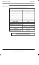
Table 4-2 shows the recommended number of PSMs for different operational
configurations.
Table 4-2 PSM operational configurations
Number of
PSMs fitted
Maximum load capability
1 Complete operation of cabinet for up to three CTUs.
2 Complete operation of cabinet for up to six CTUs.
3 Redundancy and power load sharing (further enhancing
reliability by reducing temperature of operation).
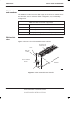
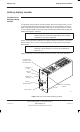
PSM module
view
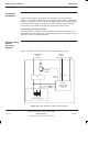
Figure 4-2 shows a view of the PSM with LEDs identified.
PSM FRONT PANEL
AIR VENTS ON
ENTIRE TOP AND
BOTTOM PANELS
GREEN LED
ACTIVE
RED LED
ALARM
OUTPUT DISABLE
SWITCH
M4 MODULE ATTACHMENT
SCREWS
Figure 4-2 View of PSM with LEDs identified