
Service Manual

GSM-204-323
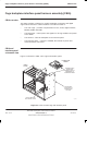
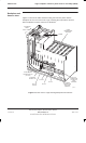
Power supply enclosure
31st Oct 01
Tech. 2–16
Technical Description: Horizon
macro
outdoor
CONTROLLED INTRODUCTION
68P02902W02-A
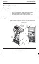
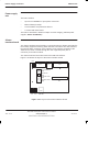
Power supply
unit
The PSU contains:
Up to three TOPSMs for input power conversion.
Minimal battery backup.
Circuit isolation and protection devices.
A control and alarm board.
The PSU is described in detail in Chapter 4 of this category (Cabinet power
supplies, Power distribution).
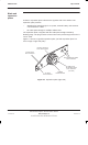
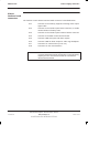
Alarms
interface board
The alarms interface board provides a connection point for alarms generated by
the auxiliary equipment housing, PSU and TMS. The alarms are then routed to
the external alarm connector of the interface panel, with the exception of the
TMS fan fail, which is routed through the main cage backplane (Fan 0
connector) to the alarm module.
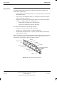
The alarms interface board also houses the TMS test switches.
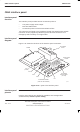
Figure 2-13 Shows the layout of the alarms interface board.
PL1 PL3
INTERNAL FANS
(SW3)
TEST OVERRIDE
(SW1)
HEATER ON
(SW2)
EXTERNAL FANS
(SW4)
PL4
PL5
PL2
PL8
PL6PL7
Figure 2-13 Layout of the alarms interface board