
Service Manual

GSM-204-323
CBIA interface panel
31st Oct 01
Tech. 2–14
Technical Description: Horizon
macro
outdoor
CONTROLLED INTRODUCTION
68P02902W02-A
CBIA interface panel
Interface panel
function
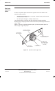
The interface panel provides internal connection points to:
The power supply unit dc output.
PSU and TMS alarms.
Connection points to all telecommunications links.
All connectors are linked to the backplane through the CBIA harness. Plastic
connector covers (supplied by Motorola) protect unused connectors from
damage by static electricity or foreign matter.
Interface panel
diagram
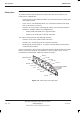
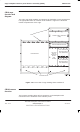
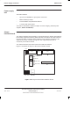
Figure 2-11 shows the functions of the interface panel connectors.
ig.239.rh
T43/BIB
AC POWER
SOCKET INPUT
(not used)
DC POWER
INPUT
GPS
(if fitted)
not used
PIX 0
EXTERNAL ALARMS
(PSU and TMS ALARMS)
PIX 1
ICS
VENTILATION
GRILLE
Figure 2-11 Layout of the interface panel
Interface panel
pinouts
Interface panel pinouts are detailed in
Installation and Configuration:
(GSM-204-423)
Interface panel cabling