
Service Manual


GSM-204-323
Outdoor cabinet structure
31st Oct 01
Tech. 2–2
Technical Description: Horizon
macro
outdoor
CONTROLLED INTRODUCTION
68P02902W02-A
Overview of
structure
description
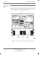
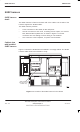
The outdoor cabinet is shown in Figure 2-2. The cabinet is itended for minimum
maintenance and maximum ease of module replacement and has access only
from the front and top.
This chapter describes the cabinet structure and the inner connections to assist
understanding the cabinet functions. There should be no need to dismantle the
cabinet beyond Field Replaceable Unit (FRU) level.
The cabinet structure components are explained in the following sections:
SURF harness
This section describes the SURF harness connections between the SURF
and the backplane and transceivers. These are not normally visible in a
fully equipped cabinet.
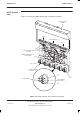
Top section
This section describes the top section holding the Tx blocks, the interface
panel, the SURF module, the number 1 ac distribution box and an ac
outlet socket.
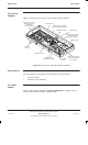
Cage backplane interface panel harness assembly (CBIA)
This section describes the CBIA. It also describes the backplane
connections between all modules, and the harness from the backplane to
the interface top panel connectors. These are not normally accessible in a
fully equipped cabinet.
Power supply enclosure
This section shows the location of the Power Supply Unit (PSU) and the
racking for customer equipment.
Doors, lid and cable shrouds
This section describes the structure and function of the doors, lid and
cable shrouds.
Space required
around cabinet
See Specifications in Chapter 1.