
Service Manual

GSM-204-323
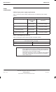
Equipment introduction and manual definition
31st Oct 01
Tech. 1–2
Technical Description: Horizon
macro
outdoor
CONTROLLED INTRODUCTION
68P02902W02-A
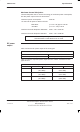
Names and
acronyms for
main cabinet
equipment
This section is intended to give the reader a basic understanding of how
components interconnect.
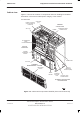
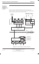
The outdoor BTS cabinet consists of a top section, a centre section (containing
the radio enclosure and the power supply enclosure), and a bottom section.
On the left side of the centre section is the radio enclosure, and this contains
the CIBA main cage.
The main cage contains the following equipment (see Figure 1-2):
A digital module shelf, located in the lower right side of the cabinet. This
contains master and optional redundant digital modules:
Fibre optic multiplexer (FMUX), 1 + 1 redundant (if required).
Main Control Unit with dual FMUX (MCUF), 1 + 1 redundant (if required).
Network Interface Units (NIUs).
An alarm board (no redundancy option).
One or two (for redundancy) BCU Power Supply Modules (BPSMs).
Up to three Power Supply Modules (PSMs) and one Circuit Breaker
Module (CBM) in the upper right part of the cage. The PSMs are load
sharing, with the third PSM providing optional redundancy.
Up to six Compact Transceiver Units (CTUs), located in the left side of the
cage.
The right side of the centre section is the power supply enclosure. It contains
the Power Supply Unit (PSU), an alarms interface board and 6 U of standard
rack space for customer specific equipment.
The PSU includes the following equipment (see Figure 1-2):
The number 2 ac distribution box, located in the upper right side of the
unit.
A dc circuit breaker panel, located in the upper left side of the unit.
An internal battery tray, located in the lower right side of the unit.
Up to three of The Outdoor Power Supply Modules (TOPSMs), in the
lower left side of the unit. The TOPSMs are load sharing, with the third
TOPSM providing optional redundancy.
A Control and Alarm Board (CAB).