
Service Manual

GSM-204-523
Replacing a CTU
31st Oct 01
Maintenance Information: Horizon
macro
outdoor
68P02902W04-A
CONTROLLED INTRODUCTION
Maint. 3–29
Replacement
procedure for
CTU
CAUTION An earthing wrist strap must be worn when handling
CTUs. An ESP earthing connection point is provided
above the leftmost PSM.
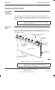
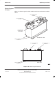
Removing a faulty CTU
To remove a CTU:
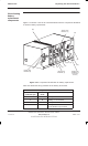
1. Locate the CTU to be replaced. CTUs are sequentially numbered, with
CTU 0 on the right, and CTU 5 on the left.
2. Disable the CTU transmit RF power by using the shutdown_device
command at the OMC-R, or from a PC connected to the MCUF.
NOTE
Refer to
Technical Description: BSS Command Reference
(GSM-100-321)
for information on usage and specific
commands.
3. When the CTU has been shutdown, check that the Tx STATUS LED (solid
yellow) is extinguished.
4. Press and release the appropriate CTU circuit breaker button on the CBM
to the out (off) position. Ensure the RADIO STATUS LED is extinguished.
WARNING
Ensure that RF power is OFF, before disconnecting RF
cables. Severe burns may result if RF power is ON when
cables are disconnected.
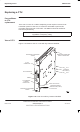
5. Unscrew the coaxial cable from the Tx OUT SMA connector at the top of
the CTU front panel.
6. Unscrew the two CTU attachment screws using an M4 Torx driver.
WARNING
The CTU weighs 5 kg. Handle with care.
CAUTION Take care to avoid damaging the CTU rear connectors
when handling outside of the cabinet.
7. Withdraw the CTU using the handle. Support the unit from underneath as
it slides out.