
Service Manual


GSM-204-523
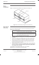
Replacing a power supply module (PSM)
31st Oct 01
Maintenance Information: Horizon
macro
outdoor
68P02902W04-A
CONTROLLED INTRODUCTION
Maint. 3–21
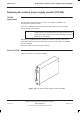
Replacing a
redundant PSM
The following procedure should be followed if three PSMs are fitted in the
cabinet:
CAUTION
Only –48/60 V dc PSMs can be used in Horizon
macro
outdoor cabinets. Ensure that the replacement PSM is of
the appropriate type (kit number SVPN1221).
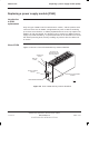
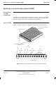
1. Verify that the switch of the replacement PSM is set to output disable.
2. Set the switch on the faulty PSM to OUTPUT DISABLE. The green LED
(ACTIVE) will go off (the green light may already be off if PSM failure has
resulted in output failure of that PSM). The red LED, if already ON due to
alarm state, will stay ON.
3. Undo the module attachment screws using an M4 Torx driver, and remove
module. The red LED will go OFF.
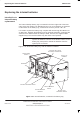
4. Insert the replacement PSM.
5. Ensure the replacement PSM is firmly in position and tighten both module
attachment screws using the M4 Torx driver. Tighten to correct torque (see
Overview of FRU replacement procedures in this chapter).
6. Set the switch to OUTPUT ENABLE. Check that the green ACTIVE LED is
lit.
BPSM
replacement
The procedure for replacing a BPSM is described in Digital module
replacement in this chapter.