
Service Manual


GSM-204-523
Overview of FRU replacement procedures
31st Oct 01
Maint. 3–2
Maintenance Information: Horizon
macro
outdoor
CONTROLLED INTRODUCTION
68P02902W04-A
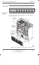
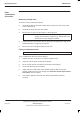
Torque values
Table 3-1 details torque values used during FRU replacement procedures.
Table 3-1 Torque values for all cabinet screws/bolts and RF connectors
Size of screw/bolt M4 M6 M8 M10 SMA N-type 7/16
Torque value (Nm) 2.2 3.4 5 10 1 3.4 25
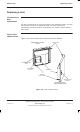
FRU view of
cabinet
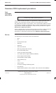
Figure 3-1 shows a cabinet with FRUs identified. Doors and lid are shown in
relevant FRU sections.
PSMs (x3)
Tx BLOCKS x3
(DCFs SHOWN AS
EXAMPLE)
SURF (Rx)
CTUs (x6)
MAIN CAGE
TEMPERATURE
SENSORS (LOCATED
ON BACKPLANE)
DIGITAL
MODULES
ALARM BOARD, MCUF,
FMUX/NIU/BPSM
CIRCUIT BREAKER
MODULE (CBM)
T43/BIB
TOPSMs
(x3)
ALARMS
INTERFACE
BOARD
CAB
INTERNAL
BATTERIES
TMS UNIT
KRONE BLOCKS
DC CIRCUIT
BREAKER PANEL
Figure 3-1 Cabinet, without doors or lid, showing FRU components