
Service Manual


GSM-204-523
General maintenance procedures
31st Oct 01
Maint. 2–6
Maintenance Information: Horizon
macro
outdoor
CONTROLLED INTRODUCTION
68P02902W04-A
Checking
normal
operation
Check normal operation by visual inspection in the following procedure:
1. Inspect the inside of the cabinet and note any signs of physical damage,
overheating, loose connections, or badly fitting components. Take
appropriate action to correct the damage, and inform the OMC-R.
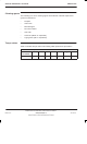
2. Note the LEDs lit on modules shown in Table 2-2 to ensure correct
functioning of the cabinet. If any red LEDs are lit, other than the door
alarm (alarm 3 on the alarm module), inform the OMC-R.
Table 2-2 Normal LED indication of cabinet modules
Equipment with LEDs Colour of LEDs lit
CTUs in locations 0 to 5 Tx status ORANGE or
Operational status GREEN
PSMs in locations 0 to 2 Top LED GREEN
Digital modules (NIU, MCUF, FMUX,
BPSM)
GREEN
Alarm module 6, 7, 8 GREEN (fans)
3 RED (as door is open)
TOPSM Input healthy YELLOW
Output healthy GREEN
CAB Radio GREEN
Comms GREEN
Status FLASHING (as door is open)
3. Verify (by listening) that the TMS recirculation fans are operating.
NOTE
In step 3 ambient air fans may also run, depending on site
conditions.